


5
12 Vdc ADC Burner Manual
10
11
6
8
1
2
7
4
9
3
5
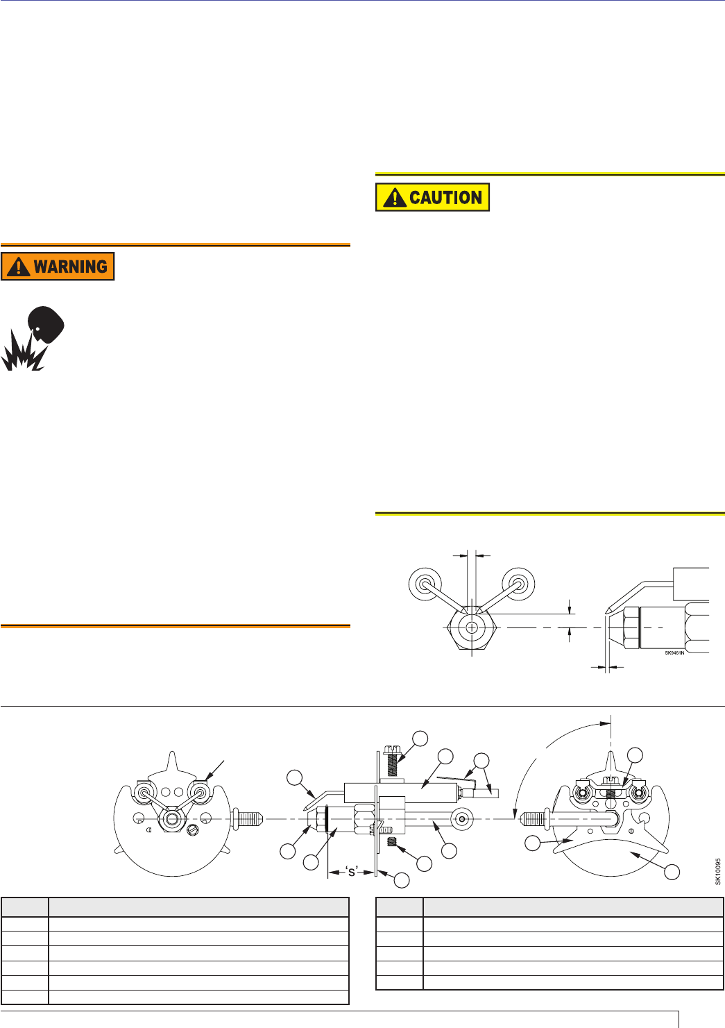
4
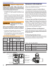
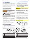
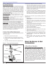
90°
Contacts to be parallel with
horizontal center line within 2°.
Electrode gap to be centered
with nozzle center.
Section: Nozzle Assembly Maintenance
Correct Nozzle and Flow
Rate Required
Incorrect nozzles and fl ow rates could
result in impaired combustion, under-
fi ring, over-fi ring, sooting, puff-back of
hot gases, smoke and potential fi re or
asphyxiation hazards.
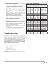
Use only nozzles having the brand, fl ow rate (gph), spray
angle and pattern specifi ed by the appliance manufacturer.
Follow the appliance manufacturer’s specifi cations for the
required pump outlet pressure for the nozzle, since this
affects the fl ow rate.
y Nozzle manufacturers calibrate nozzle fl ow rates at
100 psig.
y When pump pressures are higher than 100 psig, the
actual nozzle fl ow rate will be greater than the gph
stamped on the nozzle body. (Example: A 1.00 gph
nozzle at 140 psig = 1.18 gph)
Securely tighten the nozzle (90 torque inch pounds). For typical
nozzle fl ow rates at various pressures refer to Table 3.
Use care when removing or
installing an oil nozzle
A damaged nozzle could cause impaired
combustion, sooting, puffback of hot gases, oil
leakage and potential fi re or asphyxiation hazards.
y Inspect the nozzle adapter to insure that the sealing
surface is not grooved or scratched.
y To insure that the nozzle functions properly, check the
orifi ce and strainer for dirt, scratches or other damage
before installation.
y Do NOT attempt to install or remove a nozzle without
securing the adapter to prevent seriously damaging
the alignment.
y Use care when handling the nozzle line assembly
to prevent changing the electrode tip settings or
damaging the ceramic electrode insulators.
y Ensure that the electrode settings match the values
shown in Figure 2.
E. Low Firing Rate Baffl e.
The low fi ring rate baffl e (See LFRB in Replacement Parts)
reduces the air fl ow and pressure. The LFRB is sometimes
used for fi ring rates under 1.00 gph as listed in
Table 1.
Refer to the equipment manufacturer’s instructions. Do
not omit the LFRB when specifi ed. Omitting the baffl e
when specifi ed or installing the baffl e when not specifi ed
could result in poor burner performance.
Nozzle Assembly
Maintenance
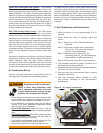
A. Replace the Burner Nozzle.
1. If applicable, remove the plastic plug protecting the
nozzle adapter threads.
2. Place a 3/4” open-end wrench on the nozzle adapter.
Insert the nozzle into the adapter and fi nger tighten.
Finish tightening with a 5/8” open-end wrench.
3. If the nozzle is already installed, remove the nozzle
line assembly to verify that the nozzle size and spray
pattern are correct for the application (per equipment
manufacturer’s information). Verify that the electrode
tip settings comply with Figure 2.
Figure 2. Electrode Tip Setting
1/4” ABOVE
CENTER
5/32” GAP
1/8” NOZZLE-TO-TIP
SPACING
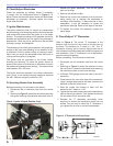
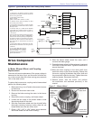
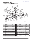
Figure 5. Nozzle, Line & Electrode Assembly
Item # Description
1 Electrode Contact (3” ATC or extension over 3”)
2 Nozzle Line
3 Spider spacer assembly
4 Static Plate
5 Electrode clamp
6 Electrode clamp retaining screws
Item # Description
7 Nozzle line setscrew
8 Electrode Insulator
9 Nozzle adapter
10 Nozzle tip
11 Electrode tip