


10
Section: Drive Component Maintenance
B. Pump Maintenance
General Pump Information
Important information - Long or oversized inlet lines may
require the pump to operate dry during initial bleeding
period. In such cases, the priming may be assisted
by injecting fuel oil in the pump gear set. Under lift
conditions, lines and fi ttings must be air tight. To assure
this, “Pipe Dope” may be applied to both the used and
unused inlet and return fi ttings. Do NOT use Tefl on tape
or compression fi ttings
Mounting Position - Beckett CleanCut pump may be
mounted in any position (except upside-down in a single
pipe installation).
Vacuum Check - A Vacuum Gauge may be installed in
either of the 1/4” NPT inlet ports.
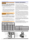
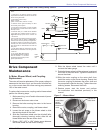
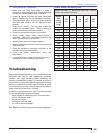
Pressure Check- When a pressure check is made, use
the nozzle port. If the bleed port is used, the reading on
the gauge should be approximately 5 psig higher than the
pressure reading on the nozzle port. See Figure 8.
Cutoff Check - To check cutoff pressure dead head a
pressure gauge in the nozzle port. Run the burner for a
short period of time. Shut the burner off. The pressure
will drop and hold above zero. Pressurized or gravity feed
installations must not exceed 3 psig on inlet line or return
line at the pump per NFPA 31. A pressure greater than 10
psig may cause damage to the shaft seal.
C. Valve Coil and Stem Replacement
To determine if the valve coil requires replacement perform
the following steps.
1. Remove the cord set from the valve.
2. Place the leads from an ohmmeter across the coil.
3. A 12Vdc volt coil should measure between 15 and
25 ohms.
4. If the meter indicates an open circuit, replace the coil.
To check pump operation perform the following.
1. Check the operating pressure by removing the copper
tubing from the nozzle line and installing a pressure
gauge in the line. With the motor running and the coil
energized, check the gauge. The pressure should read
100 psig unless otherwise stated.
2. To check the cutoff function, deadhead the pressure
gauge onto the copper connector tube attached to the
nozzle port. Run the burner for a short period of time.
Shut the burner off; the pressure should drop and hold.
To replace the coil and/or pump assembly perform the
following steps.
1. Before servicing, turn off and/or disconnect all power
to the burner.
2. Remove the copper tube assembly when replacing
the pump or when removing the coil and the tube
blocks the coil.
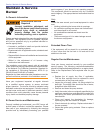
3. Using a fl at tip screwdriver, press the fl at tip into the
spring washer to prevent it from rotating.
4. Using a 10mm wrench or adjustable wrench, remove
the nut and spring washer.
5. Remove the coil by lifting it straight up.
6. Remove the two base plate screws, then the base
plate by lifting straight up.
7. Remove valve stem assembly by pulling straight up.
8. To install the new stem and coil assemblies, follow
the above steps in reverse order, tightening each
part as you go.
9. Restore power, start the burner and perform
the combustion test described previously in this
manual.
Start Up Burner & Set
Combustion
A. Basic Burner Operation
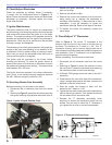
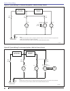
Typical Constant Duty Ignition Confi guration - With
this Beckett ADC oil burner confi guration, the motor
and igniter operate continuously while the valve that
controls oil fl ow is cycled by the switches on the power
washer. The motor is used to drive the blower and pump.
The rotational speed of the motor is determined by the
voltage supplied and the load placed on the motor. Pump
pressure and air settings are the main factors affecting
the motor load. The igniter converts battery DC voltage
into a high voltage spark to ignite the oil. The igniter is
capable of running continuously as long as the blower
wheel is circulating air across the igniter base. The pump
and solenoid valve are used to control the fl ow of oil from
the reservoir to the nozzle.
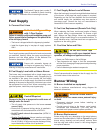
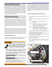
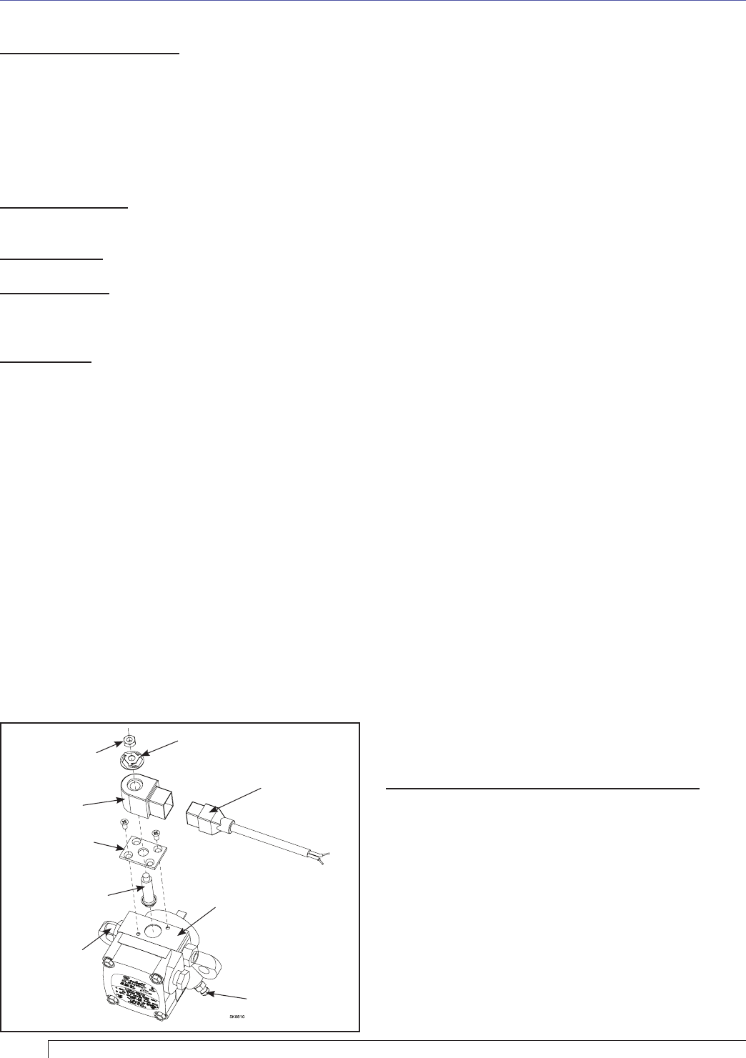
SK9810
10mm Nut
Coil
Base Plate
Stem Assembly
Nozzle Port
Fitting
Cordset
Pump Assembly
Bleed Valve
Spring Washer
Figure 8. – Pump and Valve Assemblies