


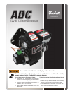
11
12 Vdc ADC Burner Manual
Section: Start Up Burner & Set Combustion
Explosion and Fire Hazard
Failure to follow these instructions could
lead to equipment malfunction and result
in heavy smoke emission, soot-up, hot gas
puff-back, fi re and asphyxiation hazards.
y Do not attempt to start the burner when excess oil has
accumulated in the appliance, the appliance is full of
vapor, or when the combustion chamber is very hot.
y Do not attempt to re-establish fl ame with the burner
running if the fl ame becomes extinguished during
start-up, venting, or adjustment.
y Vapor-Filled Appliance: Allow the unit to cool off
and all vapors to dissipate before attempting another
start.
y Oil-Flooded Appliance: Shut off the electrical power
and the oil supply to the burner and then clear all
accumulated oil before continuing.
y If the condition still appears unsafe, contact the Fire
Department. Carefully follow their directions.
y Keep a fi re extinguisher nearby and ready for use.
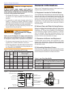
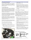
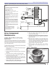
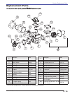
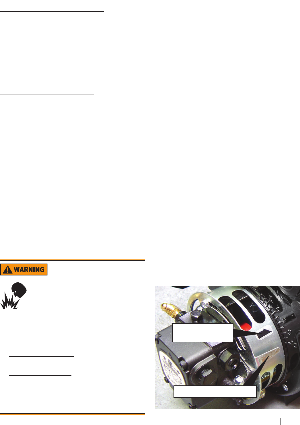
Figure 9. – Air supply components
Shutter position indicator
Air band position
indicator
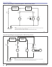
Igniter with Interrupted Duty Ignition - This optional
control circuit is available to reduce current draw on the
charging system by turning the igniter off after a fl ame has
been established. This option controls igniter operation
based on a signal from a light sensing cad cell. When light
hits the cell the control will sense a decrease in resistance
across the sensor. A few seconds delay will occur prior
to the igniter switching off. As long as suffi cient light is
reaching the cell eye, the igniter will remain off. If light is
removed from the sensor, the igniter will turn on until light
is again sensed by the cad cell.
With 7556 Primary Safety Control - The 7556 control
provides the same benefi ts as the ignition control board
as described above as well as added safety, convenience,
and performance features. It adds a valve on delay and
motor-off delay to the burner’s operation sequence that
promote clean burner operation. It has a lock-out function
that shuts the burner down if it is not operating properly.
The control adds fusing at the burner to protect against
component failures. The control also has redundant motor
relays that are checked for proper operation every heat
cycle.
Variations to the burner circuits may occur due to optional
temperature, pressure, and vacuum switches that control
burner operation. Note that when external switches
are used to control motor operation they must be sized
correctly for the rated current or a relay should be installed
to isolate the switches from the motor’s full load current.
B. Combustion Set-up
As soon as burner motor starts rotating bleed all the air
from the pump. (Required with single-pipe systems.)
To bleed the pump, attach a clear plastic hose over the
vent fi tting. Loosen the fi tting and catch the oil in an empty
container. Tighten the fi tting when all air has been purged
from the supply system. Note: If the burner stops after a
fl ame is established, the unit probably requires additional
bleeding. Continue to bleed the system until the pump is
primed and a fl ame is established when the bleed valve
is closed.
C. Set Combustion with Instruments
1. Allow the burner to run for approximately 5 to 10
minutes.
2. Follow these four steps to properly adjust the
burner:
Step 1: Adjust the air until a trace smoke level is
achieved.
Step 2: At the trace of smoke level, measure the
CO
2
(or O
2
). This is the vital reference
point for further adjustments.
Step 3: Increase the air to reduce CO
2
by 1
percentage point (O
2
will be increased by
approximately 1.4 percentage points).
Step 4: Recheck the smoke level. It should be zero.
3. This procedure provides a margin of reserve air to
accommodate variable conditions.
4. Once the combustion level is set, tighten the fasteners
on the air band and air shutter.
5. Start and stop the burner several times to ensure
satisfactory operation.
6. Test the equipment safety controls to verify
they function according to the manufacturer’s
specifi cations.