


4
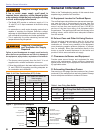
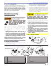
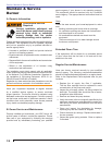
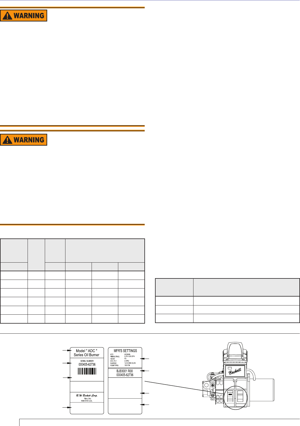
Figure 1. Typical Burner Nameplate
Table 1. Low Firing Rate Baffl e
Head Type
Low Firing Rate Baffl e (if specifi ed)
F0 up to 0.65 gph
F3 up to 0.85 gph
F4 or F6 up to 0.90 gph
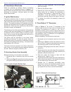
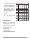
Table 2. Air Tube Combination (ATC) Codes
Firing
Rate
GPH
Head
Static
Plate
Size
ATC Codes for Usable Air
Tube Lengths:
(‘A’ in inches see Fig. 2)
min-max inches 4-1/2 5-3/8 6-5/8
0.40 - 0.75 F0 3-3/8U AF44XR AF53XR AF65XR
0.75 - 1.25 F3 2-3/4 AF44XN AF53XN AF65XN
0.85 - 1.35 F4 2-3/4 AF44WH AF53WH AF65WH
0.85 - 1.65 F6 2-3/4 AF44YB AF53YB AF65YB
1.10 - 2.00 F12 2-3/4 AF44XO AF53XO AF56XO
1.65 - 2.50 F22 2-3/4 AF44XP AF53XP AF56XP
*See page 3 for capacity and voltage specifi cations.
Section: General Information
Adequate Voltage Required
A low or erratic power supply could result in
impaired burner operation, severe delayed ignition
or an explosion inside the heat exchanger resulting
in a burn and/or asphyxiation hazard.
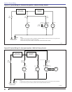
y The Model ADC requires a continuous supply of 11 to
16 volts DC at 15 amps measured at the burner during
operation.
y An automotive or small engine charging system that is
capable of supplying the required continuous voltage/
amperage is recommended with certain road equipment,
such as asphalt hot patchers and similar applications.
y This is especially true while maintaining nominal load
temperatures during idle periods.
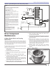
Adequate Combustion
and Ventilation Air Supply
Required
Failure to provide adequate air supply could seriously
affect the burner performance and result in damage to
the equipment, asphyxiation, explosion or fi re hazards.
y The burner cannot properly burn the fuel if it is not
supplied with a reliable combustion air source.
y Follow the guidelines in the latest editions of the NFPA
31 and CSA-B139 regarding providing adequate air
for combustion and ventilation.
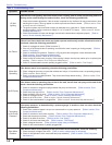
General Information
Refer to the Troubleshooting section of this manual when
experiencing a possible fault condition.
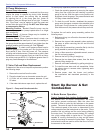
A. Equipment Located in Confi ned Space
The confi ned space should have two permanent openings:
one near the top of the enclosure and one near the
bottom of the enclosure. Each opening shall have a free
area of not less then one square inch per 1,000 BTU’s
per hour of the total input rating of all equipment within
the enclosure. The openings shall have free access to the
building interior, which should have adequate infi ltration
from the outside.
B.
Exhaust Fans and Other Air-Using Devices.
Size air openings large enough to allow for all air using
devices in addition to the minimum area required for
combustion air. If there is any possibility of the equipment
room developing negative pressure (because of exhaust
fans, for example), either pipe combustion directly to the
burner or provide a sealed enclosure for the burner and
provide it with its own combustion air supply.
C. Clearances to Burner and Equipment
Provide space around burner and equipment for easy
service and maintenance. Check minimum clearances
against those shown by the equipment manufacturer and
by applicable codes.
D. Exhausting Hazardous Fumes
See warning on this page. Also be conscious of any fumes
produced by the materials that are being heated. Always
ensure adequate ventilation to exhaust all fumes.
SK10090
PUMP PRS:100 PSI
Made in the U.S.A.
Elyria, Ohio
R.W.Beckett Corp.
000405-62736
BJB3001 R00
Model " AFG "
SERIAL NUMBER
000405-62736
Series Oil Burner
MFR'S SETTINGS
F3HEAD:
STC PLT:
NOZZLE:
FIRING RNG:
ATC:
0.75-1.35 GPH
1.0 X 80B DLVN
2-3/4U
AF65XN
RWB
ELYRIA
OHIO U.S.A.
General Model Information
Serial Number
Including Date Code
Rating Information
Primary Group
and Fuel Oil
R.W. Beckett
Manufacturer’s Settings
R.W. Beckett Specification
Number and Revision
Can Be Customized by
Individual Specification
State & Local Approvals