


22 Encore VPx Installation Guide • 08-0311105-00 Rev 00
båÅçêÉ=smñ=fåëí~ää~íáçå=dìáÇÉ
Installation
3. Rack mount processor #4.
4. Connect Ethernet from processor #4 to the Ethernet Switch.
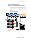
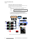
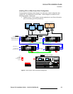
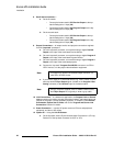
5. Source Connections — connect DVI outputs from processors one, two and three
to processor #4’s scaler inputs:
~ Connect processor #1 DVI Program 2 output to processor #4 input 1A.
~ Connect processor #1 DVI Preview 2 output to processor #4 input 1B.
~ Connect processor #2 DVI Program 2 output to processor #4 input 2A.
~ Connect processor #2 DVI Preview 2 output to processor #4 input 2B.
~ Connect processor #3 DVI Program 2 output to processor #4 input 3A.
~ Connect processor #3 DVI Preview 2 output to processor #4 input 3B.
6. Output Connections —
~ Connect processor #4’s analog or digital Preview Output to the input of
your widescreen preview monitor.
~ (Optional, for video recording) Connect processor #4’s analog or digital
Program Output 1 or 2 to the input of the ImagePRO. Connect the
ImagePRO’s output to the input of your recorder. Refer to the
“ImagePRO User’s Guide” for connection and setup details.
7. Power Connection — connect AC power cords to the AC Power connectors on
the rear of processor #4, the monitor and the ImagePRO.
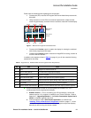
8. System ID — Using the Unit ID Selector, set the ID of processor #4 to 4.
9. Power On — Refer to Chapter 6 of the Encore Presentation System User’s
Guide for all power on instructions.
Note
Program 2 output is used because it is a clean feed, without
any edge feathering or data doubling in the signal.
Note
Each processor must have a unique ID.
Important
In order to properly configure processor #4 and its Preview
output, several important setup steps must be taken at the
Controller. For full instructions, in Chapter 3 of the Encore
Presentation System User’s Guide, refer to the
“Completing Wide Screen Preview Setup” section.