


12 Encore VPx Installation Guide • 08-0311105-00 Rev 00
båÅçêÉ=smñ=fåëí~ää~íáçå=dìáÇÉ
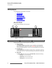
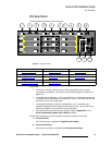
VPx Hardware
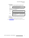
smñ=jLb=`çååÉÅíçêë
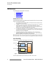
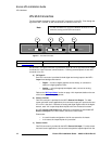
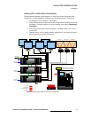
The figure below illustrates a close-up of the M/E connectors on the VPx. Even though the
figure uses M/E 1’s board, all M/E connections are identical on the VPx.
Figure 4. VPx M/E Connectors
On each M/E, one input connection is provided for layer A, one for layer B, and two “Link”
connectors for inter-Processor communications. Following are descriptions of each M/E
connector on a VPx.
a) DVI Input A
One DVI-I connector is provided for both digital and analog inputs to the M/E’s
Layer A and background channel.
~ Digital — connect a digital graphics source directly, or connect the
output of a digital graphics router.
~ Analog — using the appropriate adapter cable, connect an analog
source directly.
Refer to the “M/E Input Notes” section on page 14 for important details on the use
of this connector’s analog component.
b) Source Link Out
One DVI connector is provided for the M/E’s Source Link Output. For wide
screen and multi-screen applications, this connector loops your inputs to the next
VP or VPx in the chain. Because all analog and digital inputs reside in the digital
domain, each “link” output loops those inputs to the next Processor’s scalers.
An M/E’s Source Link Output must always be connected to its associated M/E
Source Link Input on the next chassis, and never cross-routed.
Please note:
~ In a multi-chassis configuration, the link can extend to all chassis.
~ In all cases, the looped inputs are “pre-scaler.”
c) Source Link In
One DVI connector is provided for the M/E’s Source Link Input. For wide screen
and multi-screen applications, this connector accepts the looped outputs from the
Note
The M/E connectors on a VPx are identical to those on a VP,
minus the analog and HD/SDI connectors.
DVI
INPUT 1A
DVI
INPUT 1B
OUT INSOURCE LINK 1
a b c d
a) DVI Input A c) Source Link In d) DVI Input B
b) Source Link Out