


Stove Installation (for qualified installers only) 15
© Travis Industries 93508061 4050526
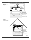
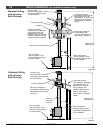
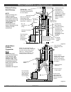
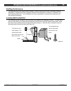
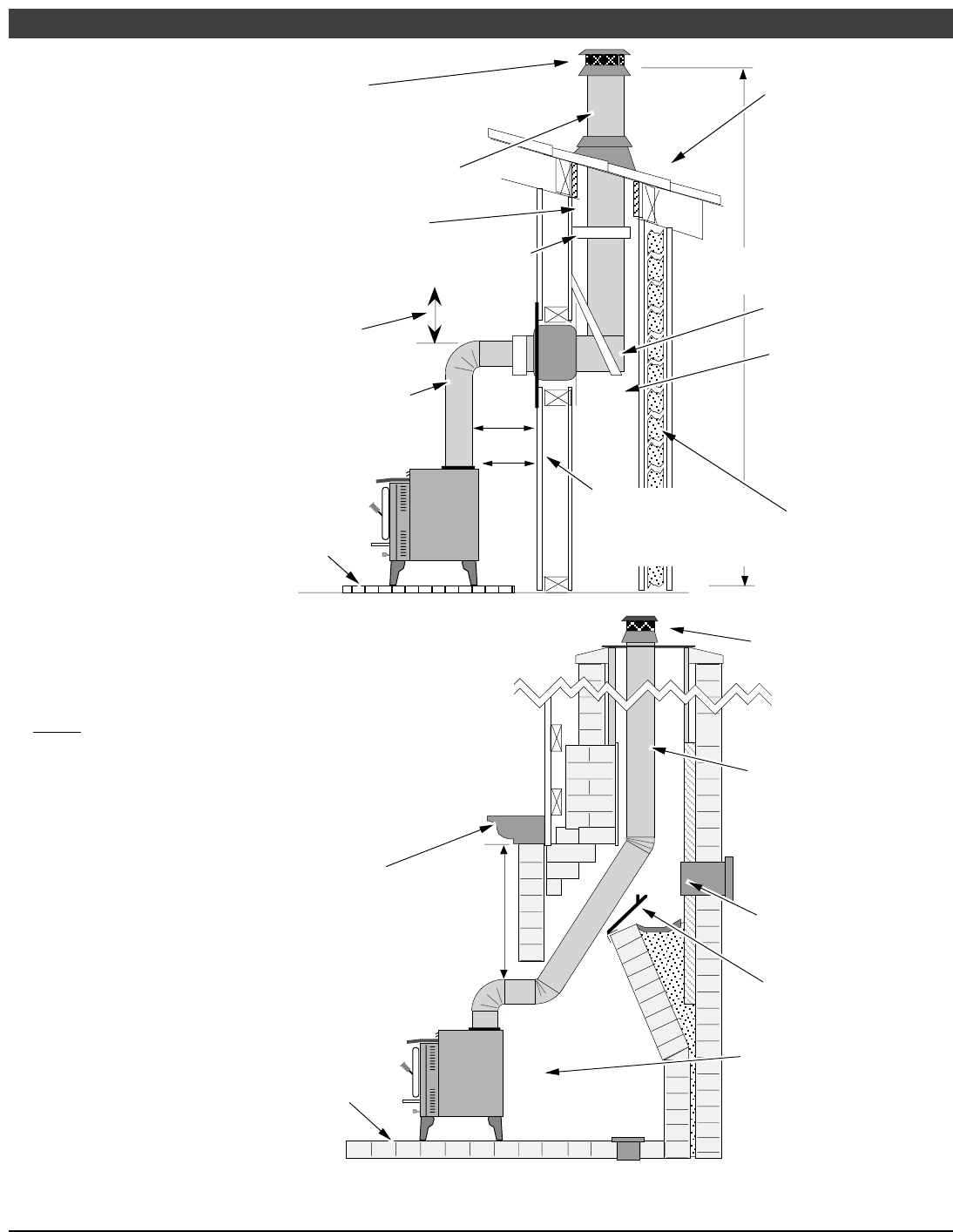
Exterior Factory
Built Chimney
NOTE:
Exterior chimneys are
subject to greater
moisture and creosote
accumulation due to the
lower temperatures. An
insulated chase will
reduce these
accumulations (the
proper clearances to the
chimney must be
maintained).
C
himney Cap
(
See the section "Chimney
T
ermination Requirements"
f
or more details)
Chimney Sections
M
inimum Air Space to
C
ombustibles (See
C
himney Manufacturer's
I
nstructions - usually 2")
Chimney Connector
Sections
Follow the chimney
manufacturer's
instructions and
clearances for roof
penetrations. A storm
collar and flashing are
required (some
require a radiation
shield).
}
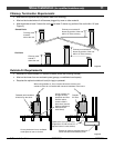
Stove Clearances
(See the section "Stove
Placement Requirements"
for more details)
}
Follow the chimney
manufacturer's
instructions and
clearances for wall
penetrations. A
wall radiation shield
(thimble) is
required.
Optional
insulated
chase
Wall Bands
and
Supports
Insulated Tee
(with cleanout )
Minimum 15'
Maximum 33'
Min. 18"
clearance to
ceiling
Floor Protection
(See "Floor
Protection
Requirements"
for details)
Figure 12
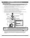
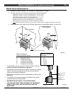
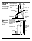
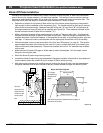
Hearth Stove
Positive
Connection
NOTE:
Most factory-built
chimney manufacturers
make stainless steel
chimney liners, either
flexible or rigid. This
provides a wide variety
of installation options.
Make sure to follow the
manufacturer's
instructions for
installation and support.
Remove damper
or wire it open
Airtight Insulated
Clean-Out
Min. 18"
Combustible
Mantle
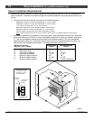
NOTE: The entire fireplace and
chimney must be clean, undamaged,
and meet all local building codes
(UBC, etc.). Damage must be
repaired prior to installation. The
chimney must be 15' to 33' tall.
Floor Protection
(See the section
"Floor Protection
Requirements"
for more details)
See the section
"Stove Placement
Requirements" for
minimum clearances
required.
The liner must be
stainless steel connector
or flexible vent. Follow
the liner manufacturer's
instructions for installation
and support.
Cap and flashing
prevents water from
entering
Figure 13