


EConnect™ TA7210
5
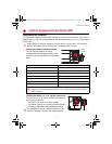
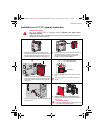
Installation in a 4-11/16'' square junction box
ELECTRICAL HAZARD
Can cause electrical shock or equipment damage. Disconnect AC power before
beginning installation.
Wiring must comply with local electrical codes. Use special CO/ALR solderless connectors if
supply wires are made of aluminum.
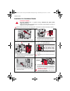
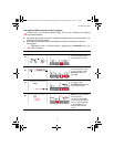
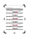
1) Mount the junction box on the wall. Punch out
knockout(s), install strain relief bushing(s) and feed
the supply wires and the heater wires. Punch out
another knockout to install the antenna (step 2).
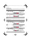
2) Remove the locknut from the antenna and peel off
the adhesive backing. Feed the antenna cable
through the knockout opening and mount the
antenna. Put the locknut and tighten.
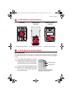
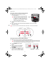
3) Clean the interior side of the junction box where the
relay will be installed. Peel off the adhesive backing
of the relay module and stick the relay inside the
junction box.
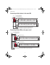
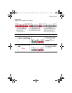
4) Connect the supply wires and heater wires to the
relay.
See page 6 if you are connecting more than one
heater.
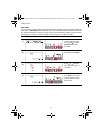
5) Insert the antenna plug in the relay receptacle until
you hear a click.
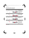
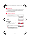
6) Install a cover plate on the junction box and
apply power to the heater. Do not put the antenna
cover back yet.
ELECTRICAL HAZARD
Can cause electrical shock. Install junction box
cover plate before applying power.
Relay wires must be at the top
To heater
L2 L1 : For 240V application
N L : For 120V application
Blue
Blue
Black
Black
Red
Red
69-2472EF-01 (Aube TA7210 System Installation Guide).book Page 5 Wednesday, June 29, 2011 1:15 PM