


14
ChannelMag
Section 2 Installation
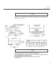
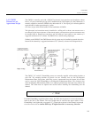
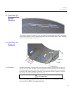
The CM2/D is normally used with a FMX167 hydrostatic level transducer and installed as shown
below. A 2-part re-
enterable gel type 4442, manufactured by 3M Company, St. Paul, Minnesota, is
normally supplied to retain the CM2/D in the hole made for it. The 2-
part gel is mixed together in
equal amounts. It makes approximately 1 gallon
(4.5 liters) of gel, which should suffice for the installation of CM2/D.
The hydrostatic level transducer must be installed in a stilling well as shown,
such that the level is
not affected by the impact pressure of the
flowing media. The hydrostatic pressure transducer may
be installed with its bottom most end above any silt build-
up at the bottom of the channel by a
suggested maximum of 0.5” (10mm). The FMX167 ha a sealed sensing diaphragm.
Similarly to the FMX167, the CM2/D mean velocity sensor may be installed to protrude above the
bottom of the channel by a suggested maximum of 0.5” (10mm), as shown in the diagram below.
The CM2/8”, 24” and 40” ChannelMag sensors are normally supplied with mounting brackets at
each side. The mounting brackets are placed over two clearance slots cut into the Magnetic
Enhancement Plates. Base plates with fixing screws, countersunk from the bottom side are then
used to secure the CM2 ChannelMag to the Magnetic Enhancement Plates. The clearance slots
allow the Magnetic Enhancements Plates to be adjusted symmetrically about the exact width of the
channel. The width must be adjusted and secured before installing the ChannelMag into the
channel.
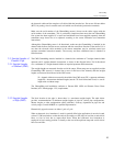
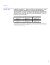
2.4.3 CM2/D
Dimensions
and
Approximate Weight
For CM2 ChannelMags supplied without ramps, the CM2 must be placed in a recess that must be
made in the bed of the channel. The recess depth must be such that the upper surface of the
ChannelMag is not higher than a suggested ½”” (12mm) above the bed of the channel, but enough
to avoid excessive silt
or similar build-up. If higher than this is necessary, then the
Note