


10
Channel / Pipe
ChannelMag
Section 2 Installation
the electrode cables and the energizer coil cable within the junction box. Do not use silicone rubber
(RTV) for potting, since it contains acetic acid which can corrode the junction box terminals.
Make sure the serial number of the ChannelMag sensor(s) shown on the cables agrees with the
serial number of the transmitter. This is particularly important when more than one ChannelMag
flow system has been supplied. If a sensor and transmitter have been supplied separately, then the
transmitter range factor has to be adjusted according to the sensor calibration (see transmitter
instructions).
Although the ChannelMag sensor is bi-directional, make sure the ChannelMag is installed in the
channel with the flow direction arrow consistent with the actual flow direction of the media. If it is
not, then the electrode cable terminals in the remote transmitter may be switched around (see
separate transmitter instruction manual). The accuracy and flow calibration factor is identical in
both directions.
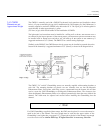
2.3.1 Straight Lengths
of Channel (CM2)
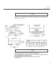
The CM2 ChannelMag must be installed in a channel with a minimum of 7 straight channel widths
upstream and 4 straight channels downstream, as shown in the diagram below. For bi-directional
use a minimum of 7 straight channel widths are required upstream and downstream.
The straight lengths are measured from the end of the ramps. When ramps are not supplied (and the
ChannelMag CM2 sensor(s) is inserted into a recess in the base of the channel), then the straight
lengths are measured from the end of the CM2 sensor.
W = channel width (not necessarily the width of the CM2 sensor)7W = upstream minimum
length2W = downstream minimum length (must be 7W for bi-directional fl ow)L = overall
length with or without ramps
The ChannelMag and installation conforms to German DIN 19559 and German Waste Water
Institute (ATV Arbeitsgruppe 1.2.5) requirements.
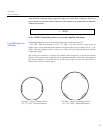
2.3.2 Straight Lengths
of Pipe (PM2)
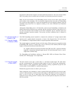
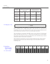
The ideal location in the pipe is where there is a maximum straight length. The table below
provides recommendations of minimum straight lengths of pipe for various pipe configurations.
Shorter lengths or other configurations affect published accuracy, dependant on pipe size and
velocity range. Consult ARKON or a qualified representative.
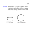
Diametrically opposite sensors are either 1 pair or 2 pair.
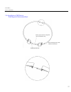
When an ultrasonic level transducer is used for partially filled pipe applications it must be located
at least 8” (200 mm) before or after the ends of the ramps to avoid drops in level due to sub-critical
flows, or rises in level due to super-critical flows. When the hydrostatic level transducer is
employed its level sensing position is virtually at the start of the upstream ramp and avoids critical
flow rises and falls.
2.3. Straight Lengths of