


11
ChannelMag
Section 2 Installation
2.3.3 Important Note
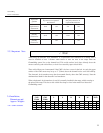
2.4.1 CM2 Sensors
Nominal
CM2
Width
Actual
CM2
Width
L S R H M
Weight
Each
in. mm. in. mm. in. mm. in. mm. in. mm.
in. mm.
in. mm.
lb kg.
8.0 200 10.0
254 40.0
1016
8.0 203 14.5
370 2.50
64 6.0 152 55 25
24.0
600 26.0
660 60.0
1520
25.0
610 18.0
460 3.12
80 12.0
305 186
85
40.0
1000
42.0
1066
80.0
2030
40.0
1020
20.0
510 3.50
89 24.0
610 355
165
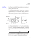
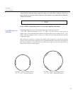
When using an ultrasonic level transducer, or a hydrostatic level transducer in a stilling well, it
must be installed at least 1 cha
nnel width before or after the ends of the ramps when the
ChannelMag sensor lies on the channel bed. This avoids surface level drops directly above the
sensors caused by sub-critical flows, or level rises caused by super critical flows.
These critical flows
are circumvented if the CM2 is let into a recess in the bed. As such, the upper
surface of the CM2 sensor may be up to 1” (25mm) above the channel bed to avoid silt build-
up.
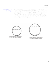
The ultrasonic level transducer may then be mounted directly above the CM2 sensor
(s). Note the
minimum dead band for the ultrasonic level transducer.
When a hydrostatic level transducer is used it is normally installed in the ramp, with its sensing at
the point of the ramp. This also avoids critical flow drops or rises in the media level above the
ChannelMag sensor.
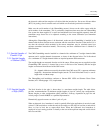
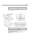
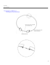
2.4 Installation,
Dimensions and
Approx. Weights
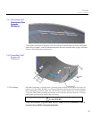
Pipe Confi
guration
Single Sensor
Number of Straight
Pipe Diameters D
Upstream
Downstream
Multiple Sensors
Number of
Straight Pipe Diameters D
Upstream Downstream
90° bend
upstream and
downstream
10 D 5 D 5 D 2 D
After a tee 15 D 5 D 8 D 2 D
Upstream
partially
closed valve
25 D 5 D 15 D 2 D
Downstream
partially
closed valve
8 D
5 D
Note