9 - 25
9.1 STEERING CONTROLS
Serial numbers 10,000 and above:
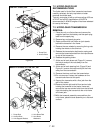
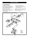
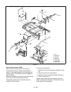
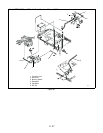
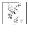
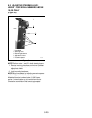
Refer to Figure 26 thru Figure 27 for Steering.
The steering controls should remain in the neutral
position unless moved by the operator. When in the
neutral position the brake rod will lock the
transmissions to prevent movement.
When the handlebars are moved the link will shift the
transmissions into forward or reverse.
The steering mechanism can be taken apart for
inspection and lubrication.
To remove the weldments:
1. Remove the link to the transmission.
2. Remove the handlebar and control arm.
3. Unscrew the flange nut that holds the weldment
onto the spacer and bearing.
4. Remove remaining hardware and slide weldment
off.
Inspect spacers bearings and pivot points for wear.
Repair or replace all worn parts. Lubricate with a high
quality grease and reassemble.
Figure 26
SECTION 9 - STEERING
4
PE0172
5
1
1
4
2
2
5
3
1. Link
2. Brake Rod
3. Eccentric
4. Weldment
5. Flange Nut
6. Handle Bar
7. Control Arm
6
7
Model EZT 915065 and 502 with Serial Numbers Above 10,000


