INSTRUCTIONS
(DO NOT BEGIN THESE PROCEDURES
UNTIL VENT HOOD HAS BEEN
INSTALLED)
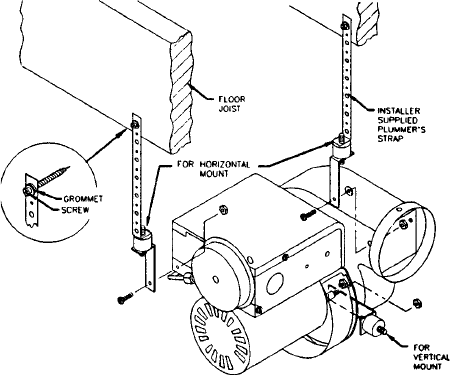
1. Remove vibration mounts, nuts and washers
from parts bag. Install on power venter as
shown in (Figure H).
2. To prevent vibration, securely support power
venter from ceiling or joist using a plumber's
strap or wire fastened to the vibration mounts.
As an alternative means of support, a wall
bracket may be used to support the underside
of the motor. (NOTE: Plumbers strap, wire or
wall bracket must be supplied by installer.)
3. Connect the power venter outlet to the inner
sleeve of the vent hood. (See page 6 for vent
piping requirements). Use the 4 pre-punched
holes in the outlet collar of the power venter as
a guide to drill 1/8" diameter holes into the vent
pipe. Fasten power venter outlet to the vent
hood inlet (or single wall pipe, depending on if
additional piping is being used between the
venter and the hood) using sheet metal screws.
4. Any vent pipe connections used after the power
venter (between it and the vent hood) will be
under positive pressure during operation. The
vent pipe must be galvanized or stainless steel
single wall vent pipe. The connections must be
sealed with high temperature silicone sealant or
aluminum vent pipe tape supplied by the
installer.
5. Install properly sized vent pipe connections
from the power venter inlet to the water heater's
outlet, avoiding elbows wherever possible.
Position the 5" to 4" reducer pipe on top of the
water heater first and then connect a 4" 90º
elbow to begin the horizontal run. Observing
this guideline will help to establish a proper
draft. When using an AQ-1 the maximum
horizontal distance from the water heater to the
power vent motor is 100 feet. Subtract 10 feet
for each added elbow.
6. Support the vent pipe in accordance with vent
manufacturer's instructions. Vent pipe is not
supplied in the power venter package, except
for the 5" to 4" reducer vent pipe in the AQ-1.
Observe the clearances associated with the
class of vent pipe used.
Installation - Electrical
1. Route the control cable from the power venter
fan along the ceiling or joists down to the gas
pressure switch, taking care not to come
closer than 6" to the vent pipe or any other
potentially hot surface. In many cases, the
gas supply piping can be used as a routing
path from the ceiling down to the controls,
using the supplied nylon ties to secure the
cable.
2. Connect the BLUE wire from the jacketed
power vent cable onto the normally open
terminal of the gas pressure switch.
(See Figure I)
FIGURE H
8


