


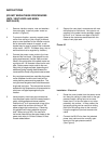

Power Vent Kit
CAUTION
1. Failure to install, maintain and/or operate the
Power Venter in accordance with
manufacturer's instruction may result in
conditions which can produce bodily injury and
property damage.
2. The Power Venter must be installed by a
qualified installer in accordance with all local
codes or, in their absence, in accordance with
the National Fuel Gas Code (ANSI
Z223.1NFPA #54), the National Electric Code
and The Occupational Health and Safety Act
(OSHA) as applicable.
3. The Power venter motor shaft must be
mounted horizontally to prevent motor bearing
wear.
4. Disconnect power supply when making wiring
connections or when working around the fan
blade and motor. Failure to do so may result
in severe personal injury and equipment
damage.
5. Make certain the power source is adequate for
the fan motor requirements. Do not add the
power venter to a circuit where the total load
is unknown.
AQ-1 Motor is 200 watts- 1.66 amps @ 120vac
Bosch-Aquastar
1. Follow installation and operating instructions
manual supplied with the water heater.
2. Before mounting water heater to wall, check
its minimum clearance requirements.
3. When using an AQ-1 the maximum
horizontal distance from the water heater to the
power vent motor is 100 feet. Subtract 10 feet
for each added elbow. Install power vent
motor as close to the termination as
possible to maintain the water heater's
optimal efficiency.
IMPORTANT: FREEZE PREVENTION TO HEATER
In cold climates the vent hood and power vent mo-
tor will not prevent infiltrating cold air to the water
heater when not in use. Be sure to install the sup-
plied backdraft AQ1FLAPPER accessory within the
vent hood on the outside of the building. If not used,
cold air can enter the vent pipe and freeze the heat-
ers heat exchanger when not in use. Such damage
is not covered under the water heater's warranty.
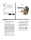
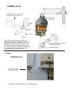
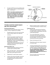
Gas Pressure Switch
Remove the gas pressure switch from the bag in the
carton and the brass 1/4" compression nut fitting which
is meant for the burner manifold tap on the heater, not
the inlet tap on the heater's gas inlet pipe (see p. 3,
Fig B). Also remove the four self-tapping screws and
the two sections of 1/4" diameter aluminum tubing from
the master carton.
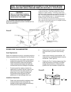
The gas pressure switch must be mounted in such a
way that the diaphragm is oriented vertically and the
aluminum tubing pieces can easily reach the manifold
pressure test nipple and the burner respectively.
It must not be mounted inside the heater. See
Figure E p.6
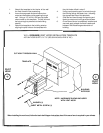
When mounting the Gas Pressure Switch: We
recommend mounting the gas pressure switch vertically
against a wall on the lower left side of the water heater.
See Figure E p.6. Because the cabinet cover is three
sided we do not recommend screwing the gas pressure
switch to the left side of it. Instead, mount the gas
pressure switch vertically against a wall on the lower left
side of the water heater. Installed in this manner all
necessary connections will be within reach and there
will be minimal interference when servicing.
2
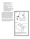
Before beginning installation review
required clearances for Water Heater,
Power Vent Motor and Vent Hood