


CAUTION
Failure to follow these installation
instructions may violate applicable
national and/or local codes
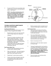
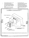
The vent system must terminate so that proper
clearances are maintained as cited in the National Fuel
Gas Code, ANSI Z223.1
"The exit terminals of mechanical vent system shall be
located not less than 7 feet above grade when located
adjacent to a public walkway. The venting system shall
terminate at least 3 feet above any forced air inlet within 10
feet. The venting system shall terminate at least 4 feet
below, 4 feet horizontally from or 1 foot above any door,
window or gravity air inlet into any building."
Also, "The vent terminal shall also not be installed closer
than 3 feet from the inside corner of an L-shaped structure,
or less than 1 foot above grade."
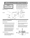
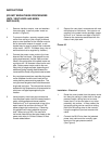
POWER VENT FAN AND MOTOR
Code Requirements
Power vent installation must be in accordance with the
following requirements of the National Fuel Gas Code:
• All portions of the vent system under positive
pressure during operation (on the downstream
outlet side of the fan motor) shall use galva-
nized or stainless steel single wall vent pipe
and be sealed to prevent leakage of flue gases.
• Provisions shall be made to interlock the
appliance(s) to prevent the flow of gas to the
main burners when the draft system is not
performing so as to satisfy the operating
requirements of the equipment for safe
performance. (Linear spillage switch: p.4)
Installation Restrictions
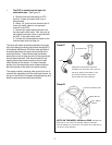
1. Power vent motor should be installed as close
to the termination of the vent system as
possible to obtain optimal appliance efficiency
and to prevent flue gas leakage.
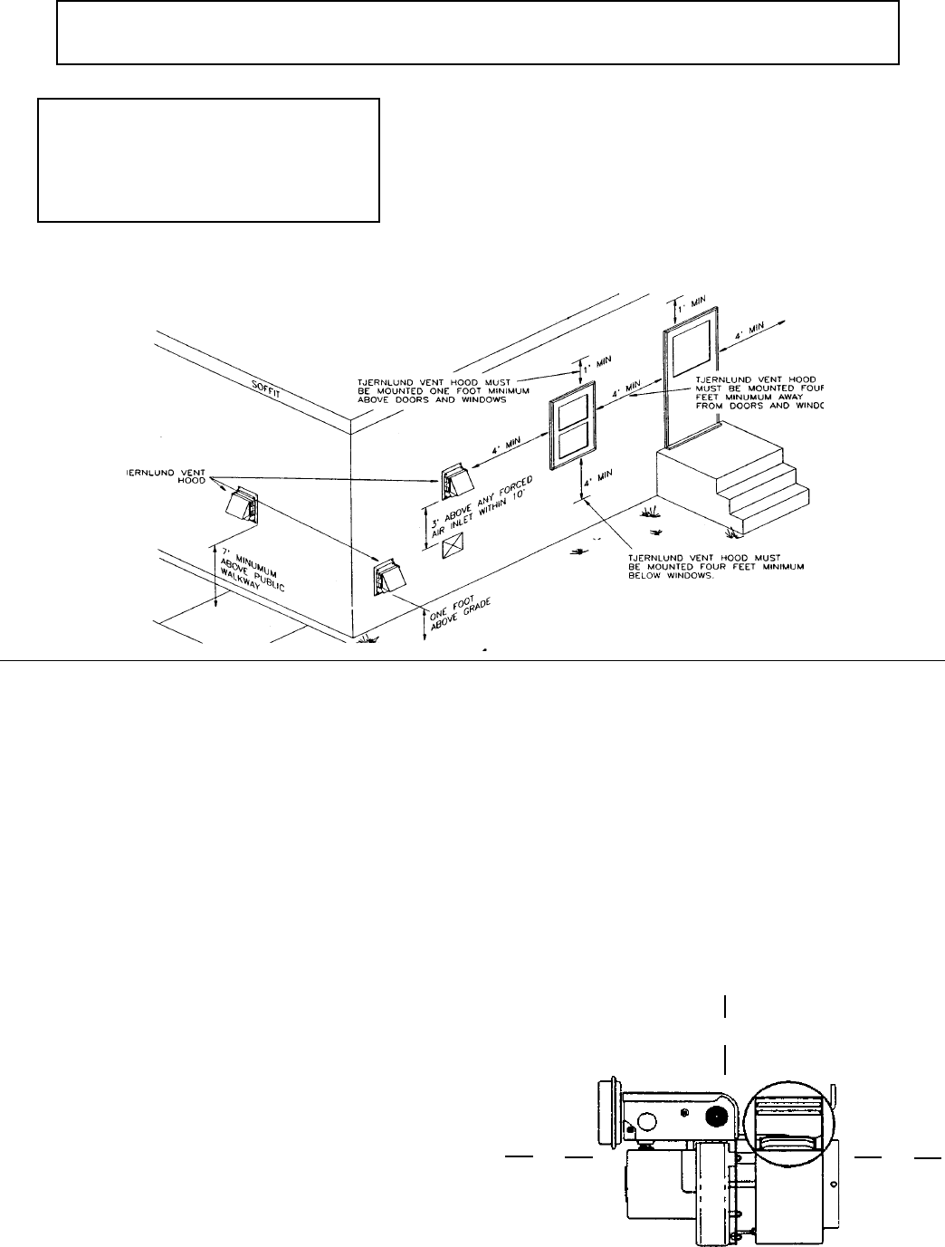
2. Power venter must be mounted with motor
shaft horizontal to prevent motor bearing
wear.
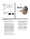
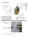
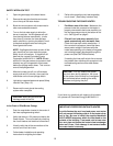
3. Power venter housing is single walled. A 6"
clearance from combustible material must be
maintained. (See Figure G)
4. Position the 5" to 4" reducer pipe on top of the
heater first and then connect a 4" 90º elbow
to begin the horizontal run. Observing this
guideline will help to establish a proper draft.
v
v
6"
v
v
6"
v
v
6"
FIGURE G
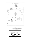
FIGURE F
NOTE: FOLLOW REQUIREMENTS IN FIGURES F & G ON THIS PAGE BEFORE
INSTALLING VENT HOOD, THEN USE TEMPLATE ON PAGE 13 TO CUT HOLE.
7