


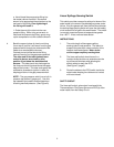
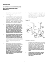
e. Hand thread the pressure tap fitting into
the heater's burner manifold. Use a small
amount of an appropriate thread sealant on the
male end of the fitting. Over tightening of
the fitting will break it.
f. Guide the end of the tube into the com-
pression fitting. While using one wrench to
hold back the pressure tap fitting, gently snug-
up the compression nut with a second wrench.
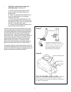
4. Bend the second piece of aluminum tubing
(from step 2) so that it will reach from the gas
pressure switch through the underneath of the
heater to an area below the burners.
Connect one end of the tube to the fitting
marked "warning" on the gas pressure switch.
The other end of the tubing should now
extend to burner area close to pilot,
position it just below the stainless steel
burners. This tube should not discharge into
the flame nor should it extend above the upper
edge of the burners. This tube vents gas to the
combustion chamber for ignition in case of a
diaphragm failure in the gas pressure switch.
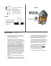
NOTE: The gas pressure switch has a built in
pressure tap marked "gauge port". Use this
tap instead of the heater's manifold tap when
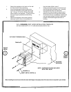
checking manifold pressure. (See Figure A)
4
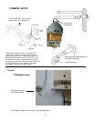
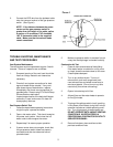
Linear Spillage Sensing Switch
This switch provides a means for safety shut down of the
water heater in the event of flue blockage or power venter
failure. If hot flue gasses spill from the draft hood diverter,
the draft spillage sensing switch will open the pilot safety
circuit and shut off all gas to the water heater. The switch
is normally closed and opens at temperatures greater
than 185º F. It has a manual reset button.
INSTRUCTIONS
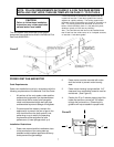
1. The entire length of the copper capillary
sensing tube is heat sensitive. The idea is to
suspend the tube within close proximity of the
heater's draft hood diverter. Note: do not
cut the copper capillary sensing tube.
2. The linear spill switch should mount in a
location where the tube can extend across the
top of the draft diverters while allowing the
switch cables to reach the ECO.
(See Figure C, page 5)
3. Route the cables to the ECO switch inside the
water heater keeping the cables out of contact
with hot surfaces.
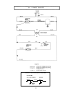
SAFETY CIRCUIT
The linear spill switch, when wired in series with the
Thermocouple or Pilot Flame Sensor and ECO(s) of the
water heater, form the Safety Circuit.