


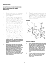
INSTRUCTIONS (SEE DIAGRAMS ABOVE)
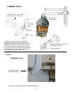
1. Mount gas pressure switch by securing it to
the chosen location with a screw in each one
of the four mounting holes.
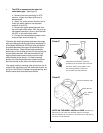
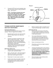
2. Use a tube cutter to make a clean cut (not
crimped) at each end of the two lengths of the
1/4" aluminum tubing. One tube must be long
enough to reach from the fitting marked
"connect to gas valve" to the pressure tap port
on the heater's burner manifold (Not to the
inlet gas pressure port of the water heater
since there will be constant gas pressure
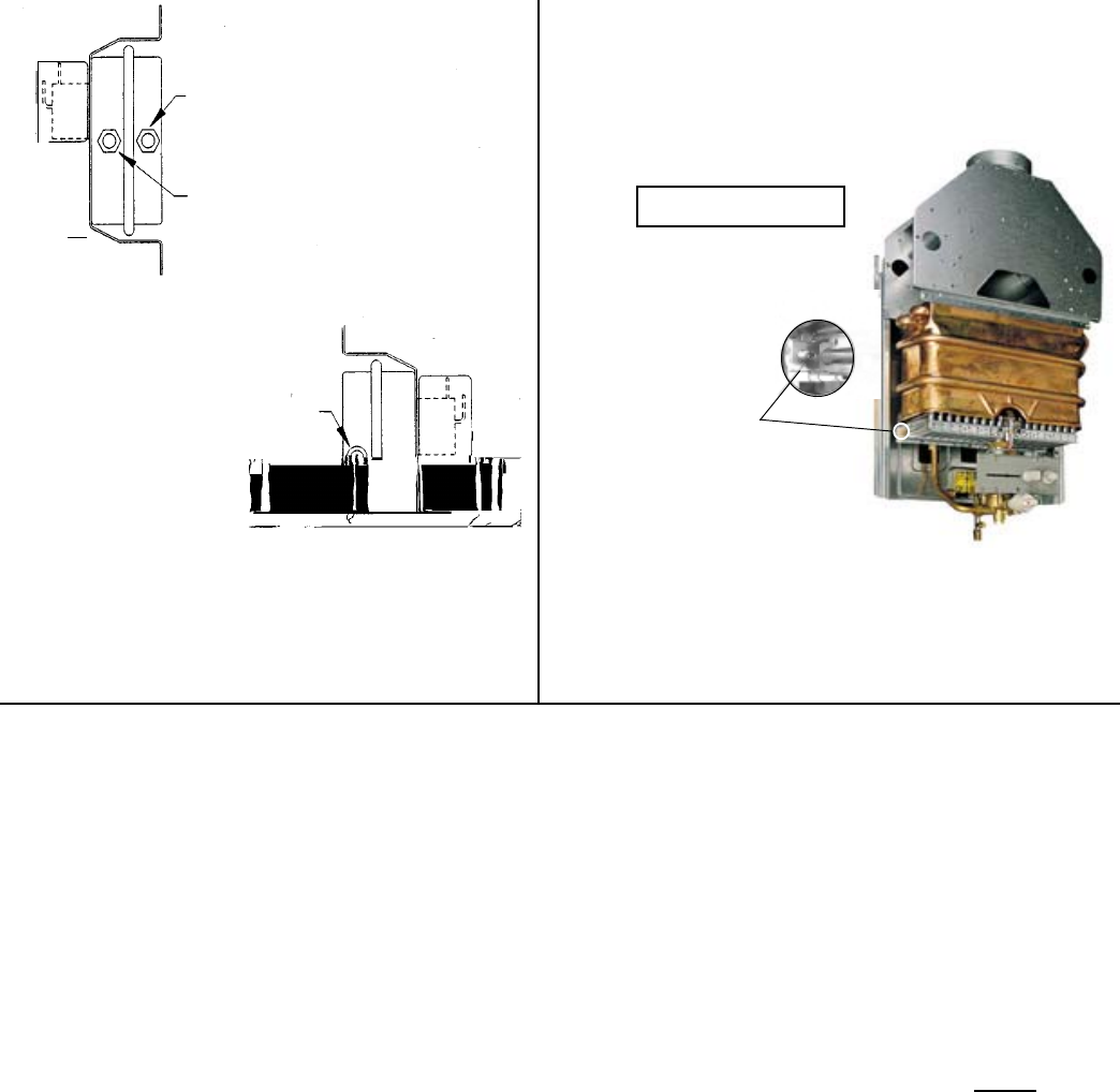
there). The tube must be long enough to enter
the bottom of the water heater front cover and
attach to the burner manifold without difficulty
(See Figure B). The second tube must be long
enough to reach from the gas pressure switch
to the burner area, but not in the pilot flame
area. Allow enough slack for very gradual
bends.
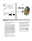
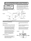
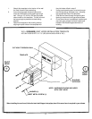
(See Figure A for gas pressure switch ports).
3. ATTENTION - Failure to follow the next series
of instructions may result in breaking a part.
a. Remove the brass pressure tap fitting from
the burner manifold of the water heater. This
fitting will not be required for reuse.
b. Bend one 1/4" aluminum tubing so that it
will run from the gas pressure switch to where
the fitting attaches to the burner manifold.
Make gradual bends - do not crimp the tube.
c. Do not connect to burner manifold, first
assemble the 1/8" NPT male by 1/4"
compression fitting with nut and sleeve to
this end of the aluminum tube. Tighten the
fitting and nut with two wrenches.
d. Separate the joint just made in step 3.c.
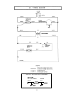
ROUTE TUBING TO PRESSURE
TAP
PORT ON THE
HEATER
'S BURNER MANIFOLD
ROUTE
TUBING TO BURNER
AREA
OR ATMOSPHERIC VENT
PRESSURE TAP-GAUGE PORT
(WHERE HEATER'S BURNER
MANIFOLD
PRESSURE CAN BE
MEASURED
)
FIGURE A
125B MODEL SHOWN
MANIFOLD
TAP
3
FIGURE B