


3
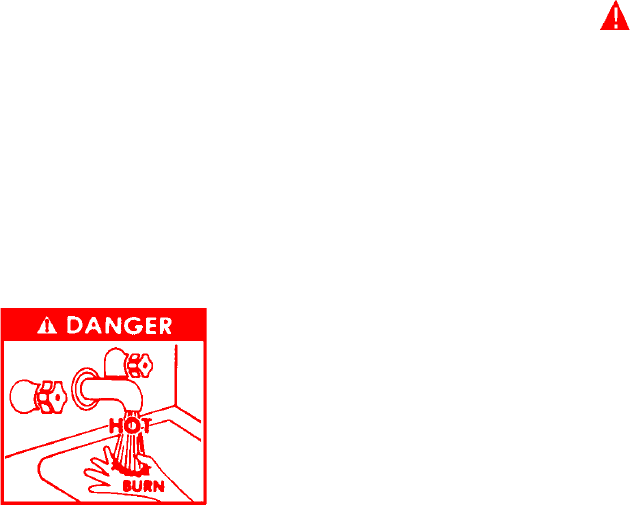
DANGER
THIS WATER HEATER IS EQUIPPED WITH AN ADJUSTABLE
THERMOSTAT TO CONTROL WATER TEMPERATURE. HOT
WATER TEMPERATURES REQUIRED FOR AUTOMATIC
DISHWASHER AND LAUNDRY USE CAN CAUSE SCALD BURNS
RESULTING IN SERIOUS PERSONAL INJURY AND/OR DEATH.
THE TEMPERATURE AT WHICH INJURY OCCURS VARIES WITH
THE PERSON’S AGE AND TIME OF EXPOSURE. THE SLOWER
RESPONSE TIME OF CHILDREN, AGED OR DISABLED
PERSONS INCREASES THE HAZARDS TO THEM. NEVER
ALLOW SMALL CHILDREN TO USE A HOT WATER TAP, OR TO
DRAW THEIR OWN BATH WATER. NEVER LEAVE A CHILD OR
DISABLED PERSON UNATTENDED IN A BATHTUB OR
SHOWER.
THE WATER HEATER SHOULD BE LOCATED IN AN AREA
WHERE THE GENERAL PUBLIC DOES NOT HAVE ACCESS TO
SET TEMPERATURES.
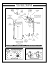
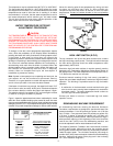
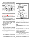
The water temperature is controlled using the Temperature Control
Button on the Display at the front of the unit (See Figure 1). This
control utilizes two temperature probes to determine the tank
temperature. The primary temperature probe is located at the top
of the tank and the other is near the water inlet.
IMPORTANT
IT IS REQUIRED THAT A QUALIFIED SERVICE TECHNICIAN
PERFORM THE INITIAL FIRING OF THE HEATER. AT THIS TIME
THE USER SHOULD NOT HESITATE TO ASK THE TECHNICIAN
ANY QUESTIONS WHICH HE MAY HAVE IN REGARD TO THE
OPERATION AND MAINTENANCE OF THE UNIT.
A CHECKLIST AND SERVICE INFORMATION section are included
at the rear of this manual. By using this checklist the user may be
able to make minor operational adjustments and save himself
unnecessary service calls. However, the user should not attempt
repairs which are not listed in this section.
WATER TEMPERATURE CONTROL
PAGE
Closed System ................................................................................ 13
Water (Potable) Heating & Space Heating ...................................... 13
Heater Wiring ..................................................................................14-15
OPERATION .......................................................................................... 15
Sequence of Operation .................................................................. 15
Self Diagnostic Controller ............................................................... 15
Gas Value LEDs Flashing ............................................................... 15
Error Codes ..................................................................................... 16
Fault Conditions ............................................................................... 16
No Incoming Line Voltage ................................................................ 16
No Low Voltage .......................................................................... 16
Temperature Probe Fault ................................................................. 16
E.C.O. Switch Open ........................................................................ 17
Control Bad...................................................................................... 17
Combustion Air Blockage ................................................................ 17
PRIOR TO START-UP ........................................................................... 18
Required Ability ............................................................................... 18
OPERATING INSTRUCTIONS ................................................................ 18
Adjustment Procedure (Initial Start-Up) .......................................... 18
Lighting Instructions ........................................................................ 19
Cathodic Protection ......................................................................... 20
Precautions ..................................................................................... 20
GENERAL INFORMATION .................................................................... 20
Power Burner ................................................................................. 20
High Limit ......................................................................................... 20
High Altitude Installations ................................................................ 20
MAINTENANCE .................................................................................... 20
General ............................................................................................ 20
Maintenance Schedule ................................................................... 20
Flushing ........................................................................................... 21
Draining ........................................................................................... 21
Sediment Removal ........................................................................... 21
Lime Scale Removal ........................................................................ 21
Powered Anode System .................................................................21-22
Drain Valve and Access Panels ..................................................... 22
Relief Valve ..................................................................................... 22
Internal Circulating Pump ................................................................. 22
Vent System .................................................................................... 22
INSTALLATION DIAGRAMS .................................................................23-27
Manifold Kits .................................................................................... 28
CHECKLIST AND SERVICE INFORMATION .......................................... 29
TROUBLE-SHOOTING ..........................................................................29-30
REPLACEMENT PARTS ........................................................................ 30
LIMITED WARRANTY ........................................................................... 31
PAGE
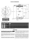
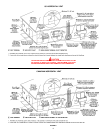
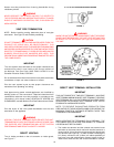
ROUGH-IN DIMENSIONS ................................................................... 2
FOREWORD ...................................................................................... 2
FEATURES ........................................................................................ 3
Water Temperature Control .......................................................... 3-4
High Limit Switch (E.C.O.) ............................................................ 4
Dishwashing Machine Requirement ............................................ 4
Circulating Pump ........................................................................... 4
INSTALLATION INSTRUCTIONS ........................................................ 4
Required Ability ............................................................................ 4
Insulation Blankets ....................................................................... 4-5
Locating The Heater..................................................................... 5
Clearances ................................................................................... 5
Hard Water ................................................................................... 5
Air Requirements ......................................................................... 6
Mechanical Exhausting of Room Air ............................................ 6
Unconfined Space ........................................................................ 6
Confined Space ............................................................................ 6
Chemical Vapor Corrosion ........................................................... 6
VENTING ........................................................................................... 6
Vent Pipe Termination ................................................................... 6
Direct Venting ............................................................................... 7-8
Direct Vent Terminal Installation ................................................... 8
Installation Sequence ................................................................... 8-9
Vertical Vent Terminal Installation ................................................ 9
Installation Sequence ................................................................... 9
Installation of Vent System .......................................................... 10
Vent Pipe Preparation................................................................... 10-11
CONTROLS AND SWITCHES ............................................................ 11
Blower Prover Switch ................................................................. 11
Blocked Outlet Prover Switch...................................................... 11
Blocked Inlet Prover Switch ......................................................... 11
Low Gas Pressure Switch .......................................................... 11
On/Off Switch .............................................................................. 11
Hot Surface Igniter ....................................................................... 11
GAS PIPING ....................................................................................... 12
Connection of Gas Pipe ............................................................... 12-13
Purging ......................................................................................... 13
Gas Meter Size - City Gases Only .............................................. 13
Gas Pressure Regulation ............................................................. 13
Gas Valves................................................................................... 13
SYSTEM CONNECTIONS .................................................................. 13
Thermometers .............................................................................. 13
Relief Valve .................................................................................. 13
Water Line Connections .............................................................. 13
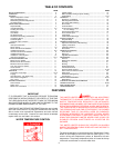
TABLE OF CONTENTS
FEATURES