


10
Heater must be protected from freezing downdrafts during
shutdown periods.
WARNING
NEVER OPERATE THE HEATER UNLESS IT IS VENTED TO
THE OUTDOORS AND HAS ADEQUATE AIR SUPPLY TO AVOID
RISKS OF IMPROPER OPERATION, FIRE, EXPLOSION OR
ASPHYXIATION.
VENT PIPE TERMINATION
NOTE: Before installing venting, determine place of vent pipe
termination. See Figure 5 and 6 before proceeding.
CAUTION
DO NOT TERMINATE THE VENTING WHERE NOISE FROM THE
EXHAUST OR INTAKE WILL BE OBJECTIONABLE. THIS
INCLUDES LOCATIONS CLOSE TO OR ACROSS FROM WINDOWS
AND DOORS. AVOID ANCHORING THE VENT AND INTAKE PIPES
DIRECTLY TO FRAMED WALLS, FLOORS OR CEILINGS UNLESS
RUBBER ISOLATION PIPE HANGERS ARE USED. THIS
PREVENTS ANY VIBRATIONS FROM BEING TRANSMITTED INTO
THE LIVING SPACES.
IMPORTANT
The vent system must terminate so that proper clearances are
maintained as cited in local codes or the current editions of
the National Fuel Gas Code, ANSI Z223.1/NFPA 54 or the
Canadian Electrical Code, CSA C22.1.
Do not terminate the exhaust vent terminal over public area where
condensate or vapor can cause nuisance or hazard.
Plan the vent system layout so that proper clearances are
maintained from plumbing and wiring.
Vent pipes serving power vented appliances are classified by
building codes as "vent connectors". Required clearances from
combustible materials must be provided in accordance with
information in this manual under LOCATION OF HEATER and
CLEARANCES, and with National Fuel Gas Code and local Codes.
IMPORTANT
Plan the layout of the vent system backwards from the vent
termination to the appliance.
WARNING
USE ONLY THE VENT TERMINALS SUPPLIED WITH THIS UNIT.
TERMINATION OF A VENT SYSTEM WITH A DEVICE OTHER THAN
THE SUPPLIED VENT TERMINATIONS WILL AFFECT SYSTEM
PERFORMANCE AND RESULT IN A SAFETY HAZARD.
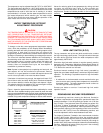
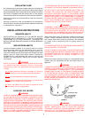
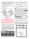
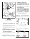
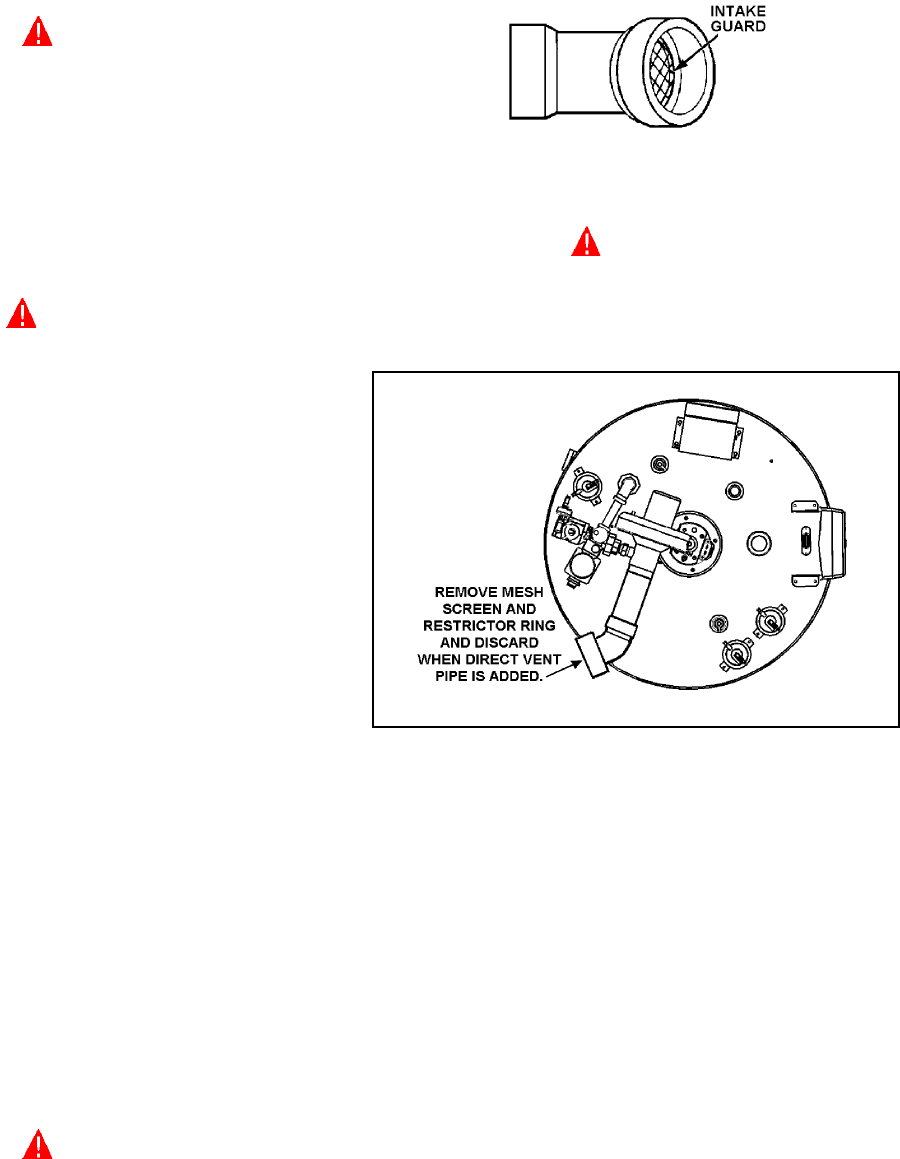
DIRECT VENTING
The air intake provided on the unit contains an intake guard,
see Figure 7.
3"x 4" 45° PVC ELBOW WITH INTAKE GUARD
FIGURE 7.
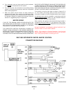
WARNING
WHEN THE UNIT IS TO BE SETUP AS A DIRECT VENT, THE INTAKE
GUARD MUST BE REMOVED. THE INLET VENT PIPE MAY THEN
BE GLUED TO THE AIR INTAKE (see Figure 8) PROVIDED ON
THE UNIT.
FIGURE 8.
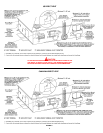
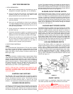
DIRECT VENT TERMINAL INSTALLATION
IMPORTANT
THIS UNIT CONSISTS OF TWO VENT TERMINALS - AN INTAKE
VENT TERMINAL AND AN EXHAUST VENT TERMINAL. THE INTAKE
VENT TERMINAL IS A 3" 45° PVC ELBOW WITH A DOME SHAPE
SCREEN AND THE EXHAUST VENT TERMINAL IS A 3" 45°PVC
ELBOW WITH A MESH WIRE SCREEN.
NOTE: TO PREVENT EXHAUSTING PRODUCTS FROM
CIRCULATING TO THE AIR INTAKE IN WINDY/COLD AREAS, THE
MAXIMUM PRACTICAL DISTANCE BETWEEN THESE TWO
TERMINALS IS RECOMMENDED.
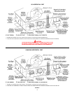
IMPORTANT
WHEN LOCATING THE TERMINALS ON A SIDEWALL, THE
FOLLOWING SPECIFICATIONS PERTAINING TO TERMINAL
LOCATION MUST BE FOLLOWED.
1. The intake vent terminal and the exhaust vent terminal must
terminate on the same exterior wall and must be located at a
minimum of 24" (61cm) from the vertical centerline of the exhaust
vent terminal (see Figure 9). In colder climates increasing the
24" (61cm) minimum to 48" (122cm) will reduce possibility of
frost over from side winds blowing exhaust vapors to the air
intake of the direct the vent and is recommended for Canada.