


13
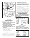
VENT PIPE PREPARATION
1. INITIAL PREPARATION
A. Make sure the solvent cement you are planning to use is
designed for the specific application you are attempting.
B. Know the physical and chemical characteristics and
limitations of the PVC, PVC cellular core, ABS or CPVC
piping materials that you are about to use.
C. Know the reputation of your pipe and cement manufacturer
and their products.
D. Know your own qualifications or those of your contractor.
The solvent welding technique of joining PVC, PVC cellular
core, ABS or CPVC pipe is a specialized skill just as any
other pipe fitting technique.
E. Closely supervise the installation and inspect the finished
job before start-up.
F. Contact the manufacturer, supplier, or competent consulting
agency if you have any questions about the application or
installation of PVC, PVC cellular core, ABS or CPVC pipe.
G. Take the time and effort to do a professional job. Shortcuts
will only cause you problems and delays in start-up. The
majority of failures in these systems are the result of
shortcuts and/or improper joining techniques.
2. SELECTION OF MATERIALS
PRIMER
It is recommended that Tetrahydrofuran (THF) be used to prepare
the surfaces of pipe and fittings for solvent welding. Do not use
water, rags, gasoline or any other substitutes for cleaning PVC
cellular core, ABS or CPVC surfaces. A chemical cleaner such as
MEK may be used.
CEMENT
The cement should be a bodied cement of approximately 500 to
1600 centipoise viscosity containing 10-20% (by weight) virgin PVC
material solvated with tetrahydrofuran (THF). Small quantities of
dimethyl formamide (DMF) may be included to act as a retarding
agent to extend curing time. Select the proper cement; Schedule
40 cement should be used for Schedule 40 pipe. Never use
all-purpose cements, commercial glues and adhesives or
ABS cement to join PVC or CPVC pipe and fittings.
SAFETY PRECAUTION: PRIMERS AND CEMENTS ARE
EXTREMELY FLAMMABLE AND MUST NOT BE STORED OR USED
NEAR HEAT OR OPEN FLAME. ALSO, USE ONLY IN A WELL-
VENTILATED AREA.
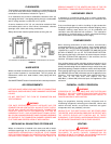
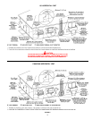
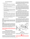
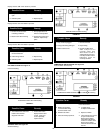
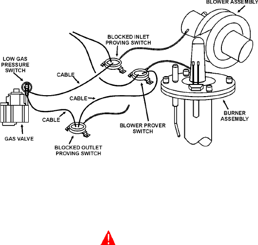
CONTROLS AND SWITCHES
The BTH-300 & 400 are equipped with four pressure switches.
These switches are essential to the safe and proper operation of
the unit. All switches are wired in series. The controller is set up
to shut the unit down whenever there is a failure of any of the
switches. It is important to understand the purpose of each switch.
BLOWER PROVER SWITCH
The Blower Prover Switch is provided on the heater to verify that the
fan is operating. It is a positive pressure switch whose electrical
contacts are normally open. When the fan increases the pressure
in the burner, the pressure switch will allow the electrical contacts
to close. The pressure switch is connected to the burner tap by a
piece of tygon tubing. This tubing must be connected in order for
the switch to change the electrical contacts. The controller requires
that the electrical contacts on this air flow switch be open before it
will allow the blower to come on. See Figure 13.
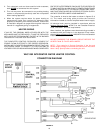
BLOCKED OUTLET PROVER SWITCH
The Blocked Outlet Prover Switch is set up to shut the unit off
when a build-up of positive pressure in the exhaust vent pipe
occurs. This switch is a positive pressure switch that requires an
increase in pressure to change the electrical contacts from
normally closed to open. When this switch prevents the unit from
igniting, most likely the exhaust is blocked by some means. Check
to see if the condensate is allowed to flow freely from the exhaust
elbow and for obstructions in the exhaust venting and exhaust
vent terminal. See Figure 13.
BLOCKED INLET PROVER SWITCH
The Blocked Inlet Prover Switch is set up to shut the unit off when
a build-up of negative pressure in the intake vent pipe occurs. This
switch is a negative pressure switch that requires an increase in
negative pressure to change the electrical contacts from normally
closed to open. The switch is connected to the pressure tap on the
flange connected to the inlet of the blower. When this switch
prevents the unit from igniting, most likely the intake is blocked by
some means. Check to see if there is no more than eighty (80)
equivalent feet (24.8m) of four inch PVC vent pipe on the intake. Also
verify that the intake and intake vent terminal is free of obstructions
that may prevent air from entering the unit. See Figure 13.
LOW GAS PRESSURE SWITCH
The Low Gas Switch (LGS) is a single-pole, normally open
pressure switch that will close its contacts when a rising pressure
of 5.0 in. W.C. (1.25Kpa) is encountered. The contacts will open
when the pressure falls below the fixed set point of 5.0 in. W.C.
(1.25Kpa) The LGS monitors the gas supply pressure to the heater.
If the gas supply falls below 5.0 in. W.C. (1.25Kpa), the main
burner is extinguished (if heater is running) or the heater will not
start up. NOTE: LOW GAS IS LOCATED ON INLET SIDE OF GAS
VALVE. See Figure 13.
FIGURE 13.
ON/OFF SWITCH
The ON/OFF Switch is a single-pole, single-throw rocker switch.
This switch provides 120V from the line source to the heater.
CAUTION
THE WATER HEATER IS POLARITY SENSITIVE. BEFORE
APPLYING ELECTRICITY TO THIS HEATER BE CERTAIN THAT
SUPPLY NEUTRAL WIRE TO GROUND CHECK INDICATES ZERO
VOLTAGE.