


16
2. Toxic chemicals, such as those used for boiler treatment,
shall
NEVER be introduced into this system.
3. This unit may never be connected to any existing heating
system or component(s) previously used with non-potable
water heating appliance.
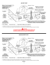
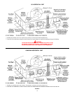
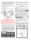
4. When the system requires water for space heating at
temperatures higher than required for domestic water
purposes, a tempering valve must be installed. Please refer
to installation diagrams on pages 23 through 28 in back of
manual for suggested piping arrangements.
HEATER WIRING
IF ANY OF THE ORIGINAL WIRE AS SUPPLIED WITH THE
APPLIANCE MUST BE REPLACED, IT MUST BE REPLACED
WITH 105°C OR ITS EQUIVALENT, EXCEPT IN THE BURNER
HOUSING. IN THIS CASE USE 200°C WIRE.
THE COMPUTER CONTROL REQUIRES A SOURCE OF
STABLE CLEAN ELECTRICITY FOR PROPER OPERATION.
INSTALLING THE HEATER ON A BRANCH CIRCUIT THAT HAS
ELECTRONIC NOISE, IS SUBJECT TO FLUCTUATIONS IN
VOLTAGE LEVEL OR HAS AN APPLIANCE WHICH GENERATES
EMF OF RFI INTERFERENCE CAN CAUSE THE CONTROLLER
TO MALFUNCTION. A HIGH QUALITY POWER CONDITIONER
MUST BE INSTALLED IF THE ABOVE CONDITIONS EXIST.
MALFUNCTIONS CAUSED BY A POOR ELECTRICAL SUPPLY
ARE NOT COVERED UNDER YOUR WARRANTY.
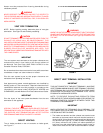
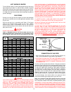
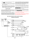
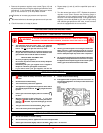
The controller is wired to the heater as shown in figures 15 &
16. The model and rating plate provides the electrical
information needed to size the complete heater branch supply.
All electrical work must be installed in accordance with the
National Electrical Code, NFPA 70 or the Canadian Electrical
Code, CSA C22.1 and local requirements.
When installed, the appliance must be electrically grounded in
accordance with local codes or, in the absence of local codes,
with the
National Electrical Code, ANSI/NFPA 70 or the Canadian
Electrical Code, CSA C22.1.
DO NOT ENERGIZE THE BRANCH CIRCUIT BEFORE THE
HEATER TANK IS FILLED WITH WATER.
NOTE: This controller is Polarity Sensitive. If the Hot and
Neutral Supply Voltage is reversed, the controller will not sense
flame. Verify polarity before connecting the unit.
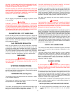
FIGURE 15.
WHC1202 INTEGRATED WATER HEATER CONTROL
CONNECTION DIAGRAM