


12
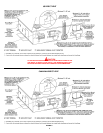
2. Drill a pilot hole approximately 1/4" (6 mm) outside of the marked
circle. This pilot hole is used as a starting point for a saws-all or
sabre saw blade. Cut around the marked circle staying
approximately one quarter inch outside the line. (This will allow
the vent pipe to easily slide through the opening). The resulting
gap will be covered by the roof boot/flashing.
3. Suspend the pipe through center of hole using proper support.
4. Slide roof boot or equivalent flashing over pipe and secure roof
boot equivalent flashing to roof.
5. Seal around flashing.
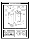
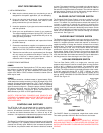
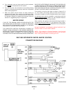
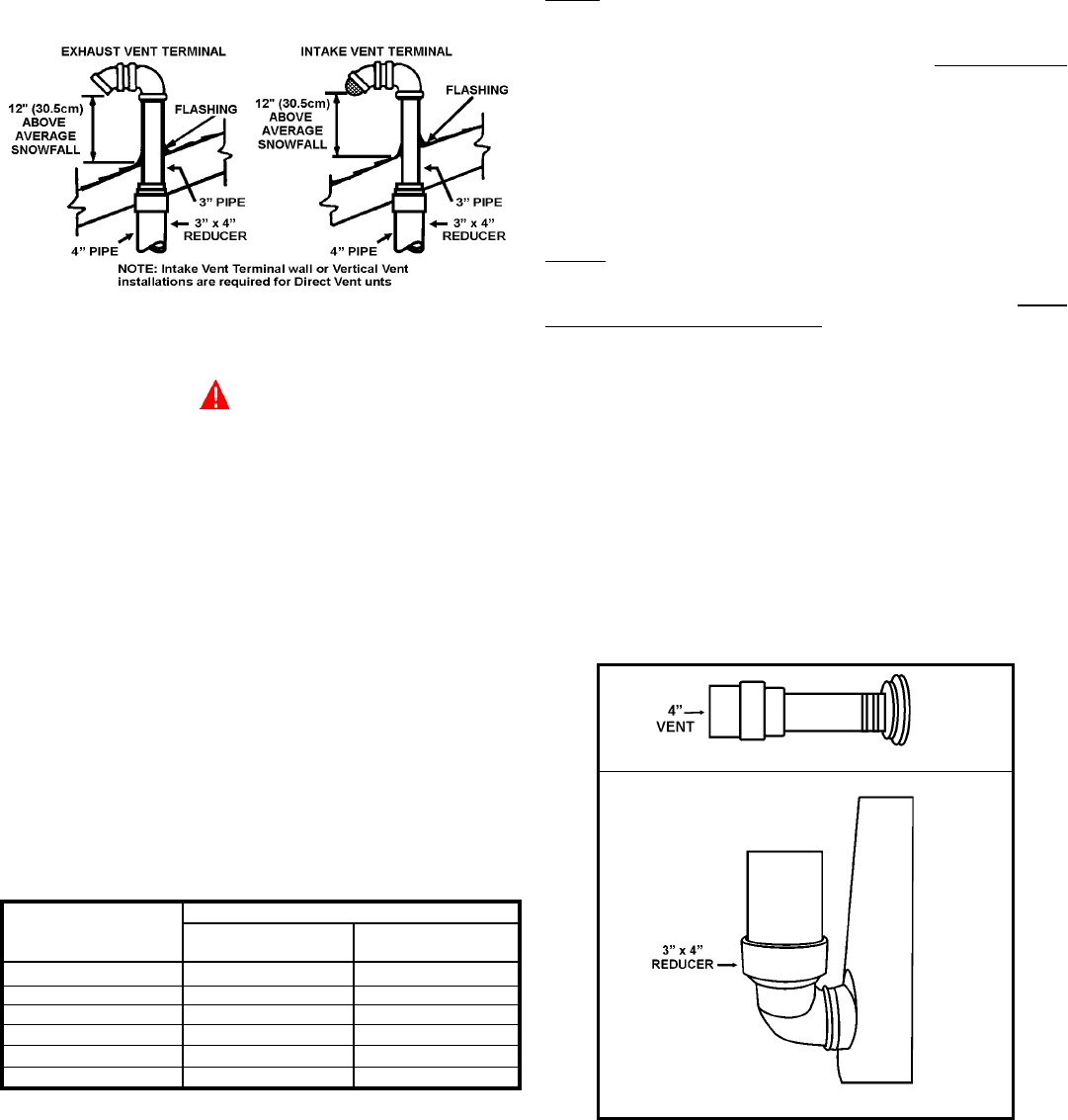
6. Terminate intake terminal and exhaust vent terminal facing
down. See Figure 11.
FIGURE 11.
INSTALLATION OF VENT SYSTEM
WARNING
THE OPTIONAL INTAKE VENTING ARRANGEMENT AND THE
EXHAUST VENTING ARRANGEMENT MUST BE INSTALLED TO
RUN DIRECTLY TO THE OUTDOORS AND NOT IN ANY WAY BE
CONNECTED TO ANOTHER VENTING SYSTEM (I.E. FURNACE,
DRYERS OR SPACE HEATERS). IT IS CRUCIAL THAT THE
VENTING ARRANGEMENT BE KEPT SEPARATE FROM OTHER
VENTING SYSTEMS. IF THIS WARNING IS IGNORED, AND THE
SYSTEM IS VENTED INCORRECTLY, IT MAY CAUSE IMPROPER
OPERATION, FIRE, EXPLOSION, OR ASPHYXIATION.
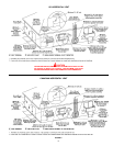
1. Plan the route of the vent system from the vent termination to
the planned location of the appliance. Layout the total vent
system to use the minimum of vent pipe and elbows possible.
2. This unit is certified for the use of 4-inch PVC pipe for venting. The
maximum length of 80-equivalent feet of 4-inch PVC pipe may be
used for the intake venting arrangement and a maximum length of
80-equivalent feet of 4-inch PVC pipe may be used on the exhaust
venting arrangement. The maximum number of 90 degree elbows
for the 4-inch venting is six (6) in the intake and six (6) on the exhaust.
A 90 degree elbow is equal to five (5) equivalent feet of 4-inch pipe.
One 90 degree elbow is equaled to two 45 degree elbows.
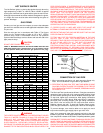
Table 2. VENT LENGTH TABLE
3. The unit is certified to a minimum amount of 4-inch pipe for the
exhaust venting arrangement of 15-equivalent feet. This is the
minimum amount of pipe required for the exhaust venting
arrangement. The intake venting arrangement is certified to
use a minimum of 0-equivalent feet of 4-inch PVC pipe.
4. The 3-inch PVC terminals supplied with the unit must be used
with the 4-inch venting by adding a 4" x 3" reducer coupling at
the venting terminals.
IMPORTANT
When multiple units are direct vented through a wall (4-inch venting),
all intake vent terminals should be no lower than the highest
exhaust vent terminal.
NOTE: This unit can be vented using only PVC (Class 160, ASTM
D-2241 Schedule 40, ASTM D-1785 ; or Cellular Core Schedule
40 DWV, ASTM F-891) , Schedule 40 CPVC (ASTM F-411), or ABS
(ASTM D-2661) pipe. The fittings, other than the
TERMINATIONS
should be equivalent to PVC-DWV fittings meeting ASTM D-2665
(Use CPVC fittings, ASTM F-438 for CPVC pipe and ABS fittings,
ASTM D-2661/3311 for ABS pipe. If CPVC or ABS pipe and fittings
are used, then the proper cement must be used for all joints,
including joining the pipe to the Termination (PVC Material). PVC
Materials should use ASTM D-2564 Grade Cement; CPVC
Materials should use ASTM F-493 Grade Cement and ; ABS
Materials should use ASTM D-2235 Grade Cement.
NOTE: for Water Heaters in locations with high ambient
temperatures (above 100°F or 38°C) and/or insufficient dilution
air, it is recommended that CPVC or ABS pipe and fittings (
MUST
USE SUPPLIED VENT TERMINAL) be used.
5. It is important that condensate not be allowed to buildup in the
exhaust vent pipe. To prevent this from happening the pipe
should be installed with a slight, 1/8 inch (3mm) per 5 feet (152
cm) of pipe maximum downward slope.
6. The vent system should be supported every 5 feet (152 cm) of
vertical run and every 3 feet (91cm) of horizontal run of vent
pipe length.
NOTE: Stress levels in the pipe and fittings can be significantly
increased by improper installation. If rigid pipe clamps are used to
hold the pipe in place, or if the pipe cannot move freely through a
wall penetration, the pipe may be directly stressed, or high thermal
stresses may be formed when the pipe heats up and expands.
Install accordingly to minimize such stresses.
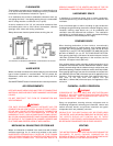
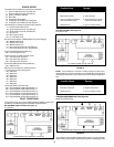
FIGURE 12.
Number 4" PVC
of 90° Maximum Maximum
Elbows Feet. of Pipe Meters of Pipe
ONE (1) 75' 22.9 m
TWO (2) 70' 21.3 m
THREE (3) 65' 19.8 m
FOUR (4) 60' 18.3 m
FIVE (5) 55' 16.8 m
SIX (6) 50' 15.2 m
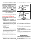
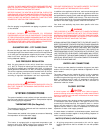
OUTLET VIEW
INLET VIEW