


17
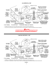
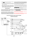
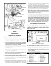
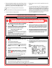
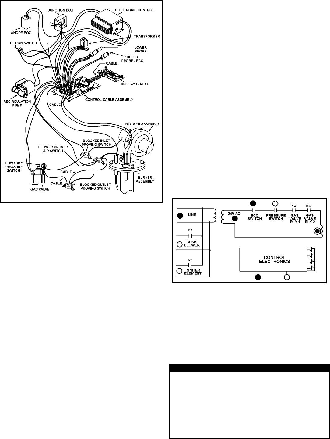
FIGURE 16.
OPERATION
SEQUENCE OF OPERATION
Typical Control/Appliance Operating Sequence
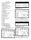
1. When the control is powered, it should first display “0”, then
the input line voltage (“120”), the calibration setting (12), then
the actual water temperature in the tank.
2. If the control determines that the actual water temperature
inside the tank is below the programmed temperature setpoint
less the differential, a call for heat is activated.
3. The control then performs selected system diagnostic checks.
This includes confirming the proper state of the air switches
and ECO limit device.
4. If all checks are successfully passed, the combustion blower
is energized for the pre-purge cycle.
5. When the pre-purge cycle is complete, power is applied to the
ignitor element for the ignitor warm-up period.
6. At the conclusion of the igniter warm-up period, the gas valve
will open, allowing gas to enter the burner chamber.
7. The igniter will remain on for a short predetermined time
period, then will be turned off.
8. After an additional 2 seconds, the control will monitor the flame
sense probe to confirm a flame is present. If a flame is not
verified within this time period, the gas valve will immediately
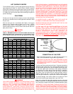
Possible Cause Remedy
1. Burner ground wire broken 1. Check wire and connection
or corroded at burner
2. Connectors unplugged 2. Check connections
3. Igniter broken 3. Replace igniter
4. Flame probe faulty 4. Replace flame probe
5. Gas shut off 5. Turn on gas supply
6. Clogged gas valve 6. Replace gas valve
7. Faulty gas valve 7. Replace gas valve
8. Defective control 8. Replace control
9. Burner improperly adjusted 9. Adjust burner
10. Dirty burner 10. Clean burner
be closed, and the blower will continue to run for approximately
10 seconds. The control will then return to step 2.
9. If a flame is confirmed, the control will enter the heating mode
where it will continue heating the tank water until the setpoint
temperature plus differential is reached. At this point, the gas
valve is closed and the control enters the post-purge cycle.
10. The combustion blower will run for the duration of the post
purge cycle to purge the system of all combustion gases.
When the post purge cycle is complete, the blower is
de-energized and will coast to a stop.
11. The control will now enter the idle state while continuing to
monitor the internal tank water temperature and the state of
other system devices. If the temperature drops below the
setpoint value less differential, the control will automatically
return to step 2 and repeat the entire operating cycle. During
this idle state, if the control detects an improper operating state
for external devices such as the ECO switch, vent switch,
pressure switch, etc., the appropriate LED(s) on the Display
Board will be illuminated indicating the nature of the fault.
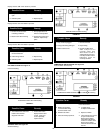
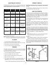
SELF DIAGNOSTIC CONTROLLER
This controller is designed for ignition lockout after three consecutive
failed attempts to light. If lockout occurs, the display lights will
match Figure 17. Along with this, a numeric message will appear
in the display. The following list of ERROR CODES illustrates
possible numeric failures.
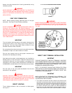
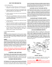
FIGURE 17.
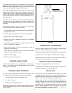
GAS VALVE LED FLASHING
This condition results from a failure to establish burner ignition
after three successive trials. In such cases:
1. Investigate the possible cause and remedy any observations.
2. Momentarily depress the button on the display panel to reset
the lockout condition.
3. Confirm proper appliance operation.