


14
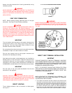
HOT SURFACE IGNITER
The Hot Surface Igniter is a device that ignites the main burner by
high temperature (>1800°F or >982°C). When 120VAC is applied
to the igniter, sufficient heat is generated to ignite the main burner.
Although improvements have been made to strengthen the igniter,
it is fragile and care must be taken when handling the igniter to
prevent breakage.
GAS PIPING
Contact your local gas service company to ensure that adequate
gas service is available and to review applicable installation codes
for your area.
Size the main gas line in accordance with Table 3. The figures
shown are for straight lengths of pipe at 0.5 in. W.C. (125Pa)
pressure drop, which is considered normal for low pressure
systems Note that fittings such as elbows and tees will add to the
pipe pressure drop.
CAUTION
DO NOT USE FLEXIBLE GAS PIPING.
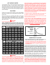
TABLE 3. MAXIMUM CAPACITY OF PIPE IN CUBIC FEET OF GAS
PER HOUR (Based upon a Pressure Drop of 0.5 inch Water Column
and 0.6 Specific Gravity Gas and max. gas pressure of 0.5 psig).
WARNING
THE HEATER IS NOT INTENDED FOR OPERATION AT HIGHER
THAN 11.0" WATER COLUMN (2.74 Kpa) FOR NATURAL GAS
AND 14.0" W.C. (3.49kPa) FOR PROPANE GAS SUPPLY
PRESSURE. HIGHER GAS SUPPLY PRESSURES REQUIRE
SUPPLEMENTAL REDUCING SERVICE REGULATION.
EXPOSURE TO HIGHER GAS SUPPLY PRESSURE MAY CAUSE
DAMAGE TO THE GAS CONTROLS WHICH COULD RESULT IN
FIRE OR EXPLOSION. IF OVERPRESSURE HAS OCCURRED
SUCH AS THROUGH IMPROPER TESTING OF GAS LINES OR
EMERGENCY MALFUNCTION OF THE SUPPLY SYSTEM THE
GAS VALVE MUST BE CHECKED FOR SAFE OPERATION. MAKE
SURE THAT THE OUTSIDE VENTS ON THE SUPPLY
REGULATORS AND THE SAFETY VENT VALVES ARE PROTECTED
AGAINST BLOCKAGE. THESE ARE PARTS OF THE GAS
SUPPLY SYSTEM, NOT THE HEATER. VENT BLOCKAGE MAY
OCCUR DURING ICE STORMS. IT IS IMPORTANT TO GUARD
AGAINST GAS VALVE FOULING FROM CONTAMINANTS IN
THE GAS WAYS. SUCH FOULING MAY CAUSE IMPROPER
OPERATION, FIRE OR EXPLOSION.
IF COPPER SUPPLY LINES ARE USED THEY MUST BE
INTERNALLY TINNED AND CERTIFIED FOR GAS SERVICE.
BEFORE ATTACHING THE GAS LINE BE SURE THAT ALL GAS
PIPE IS CLEAN ON THE INSIDE.
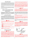
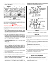
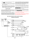
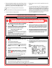
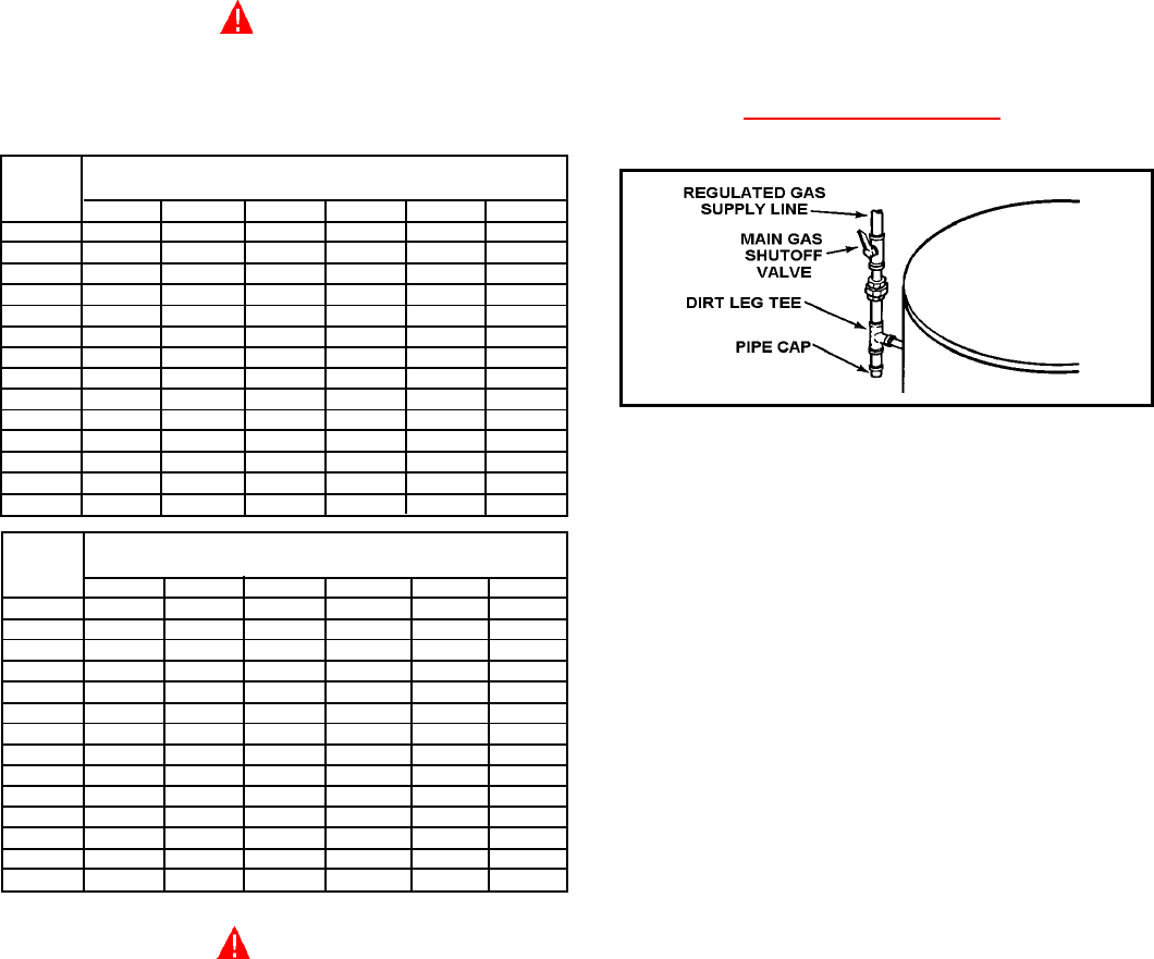
TO TRAP ANY DIRT OR FOREIGN MATERIAL IN THE GAS
SUPPLY LINE, A DIRT LEG (SOMETIMES CALLED A
SEDIMENT TRAP OR DRIP LEG) MUST BE INCORPORATED
IN THE PIPING (SEE FIG. 14). THE DIRT LEG MUST BE
READILY ACCESSIBLE AND NOT SUBJECT TO
FREEZING CONDITIONS. INSTALL IN ACCORDANCE WITH
RECOMMENDATIONS OF SERVING GAS SUPPLIERS.
REFER TO THE
NATIONAL FUEL GAS CODE OR THE NATURAL
GAS AND PROPANE INSTALLATION CODE CSA B149.1.
FIGURE 14.
CONNECTION OF GAS PIPE
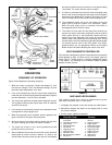
1. When connecting gas pipe to unit, apply wrench to flange only.
Note: Do not use wrench on gas valve or gas bracket.
2. PERFORM THE GAS LEAK TEST ANY TIME WORK IS DONE
ON A GAS SYSTEM TO AVOID THE POSSIBILITY OF FIRE OR
EXPLOSION WITH PROPERTY DAMAGE, PERSONAL INJURY
OR LOSS OF LIFE.
The Gas Leak Test is performed as follows: Paint pipe connections
upstream of gas control with a rich soap and water solution to test
for leaks before operating main burner. Bubbles indicate gas leak.
To stop leak, tighten pipe connections. After piping connections
are checked, turn on main burner. With main burner in operation,
paint pipe joints (including flanges), pilot gas tubing connections
and control inlet and outlet with rich soap and water solution.
Bubbles indicate gas leak. To stop leak, tighten flange screws,
joints and pipe connections. Replace part if leak can’t be stopped.
To prevent damage, care must be taken not to apply too much
torque when attaching gas supply pipe to gas valve inlet.
Apply joint compounds (pipe dope) sparingly and only to the male
threads of pipe joints. Do not apply compound to the first two threads.
Use compounds resistant to the action of liquefied petroleum gases.
DISCONNECT THE APPLIANCE AND ITS MANUAL GAS SHUTOFF
VALVE FROM THE GAS SUPPLY PIPING SYSTEM DURING ANY
SUPPLY PRESSURE TESTING EXCEEDING 1/2 PSIG (3.45Kpa).
GAS SUPPLY LINE MUST BE CAPPED WHEN DISCONNECTED
FROM THE HEATER. FOR TEST PRESSURES OF 1/2 PSIG (3.45Kpa)
LENGTH NORMAL IRON PIPE SIZES (INCHES)
IN INPUT IN THOUSANDS BTU/HR
FEET 1 1/4" 1 1/2" 2" 2 1/2" 3" 4"
10 1400 2100 3960 6300 11000 23000
20 950 1460 2750 4360 7700 15800
30 770 1180 2200 3520 6250 12800
40 660 990 1900 3000 5300 10900
50 580 900 1680 2650 4750 9700
60 530 810 1520 2400 4300 8800
70 490 750 1400 2250 3900 8100
80 460 690 1300 2050 3700 7500
90 430 650 1220 1950 3450 7200
100 400 620 1150 1850 3250 6700
125 360 550 1020 1650 2950 6000
150 325 500 950 1500 2650 5500
175 300 460 850 1370 2450 5000
200 430 800 1280 2280 4600
LENGTH NORMAL IRON PIPE SIZES (INCHES)
IN INPUT IN KW
METERS 1 1/4" 1 1/2" 2" 2 1/2" 3" 4"
3.0 410 615 1160 1845 3221 6735
6.1 278 428 805 1277 2255 4626
9.1 225 346 644 1031 1830 3748
12.2 193 290 556 878 1552 3192
15.2 170 264 492 776 1391 2840
18.3 155 237 445 703 1259 2577
21.3 143 220 410 659 1142 2372
24.4 135 202 381 600 1083 2196
27.4 126 190 357 571 1010 2108
30.5 117 182 337 542 952 1962
38.1 105 161 299 483 864 1757
45.7 95 146 278 439 776 1610
53.3 88 135 249 401 717 1464
61.0 126 234 375 688 1347