


9
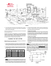
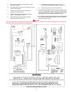
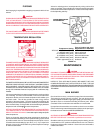
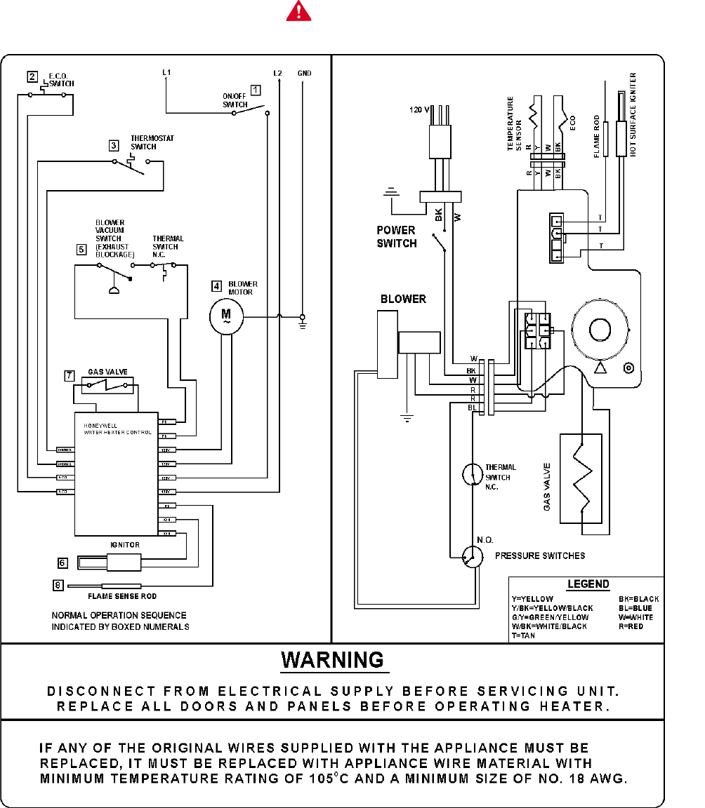
POWER VENT WIRING SCHEMATIC - FIGURE 7
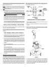
A. Remove two screws that secure side plate on control
box and remove plate.
B. Cut flexible power cord on inside of control box, as close
to inside wall as possible.
C. If flexible cord and strain relief are removed, then
opening in box must be covered.
D. Remove plastic cap in top of control box and install
suitable conduit fitting in enclosure.
E. Splice field wiring into existing wiring using code
authorized method (wire nuts, etc).
F. Be certain that neutral and line connections are not
reversed when making these connections. (See Figure 7).
G. Replace side panel and secure with two screws.
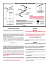
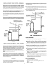
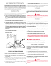
5. The blower discharge adapter is made to accept only straight sections
of 3" pipe. To start off with an elbow, a short section of the furnished
pipe, a minimum of 2 inches, must be cut and glued into the end of the
elbow that will mount on the discharge adapter (see fig. 6).
6. An 1/8 inch bead of high temperature silicone should be applied to
the circumference of the discharge adapter just before installing the
first section of pipe or elbow.
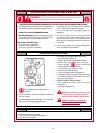
CAUTION
LABEL ALL WIRES PRIOR TO DISCONNECTION WHEN SERVICING CONTROLS. WIRING ERRORS CAN CAUSE IMPROPER AND DANGEROUS
OPERATION. VERIFY PROPER OPERATION AFTER SERVICING.