


2
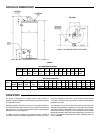
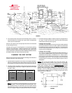
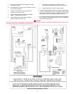
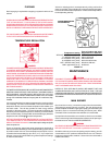
ROUGH-IN-DIMENSIONS
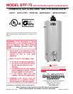
FOREWORD
The design of model BTF-75 complies with the latest version of
ANSI Z21.10.3/CSA 4.3 M98 as automatic storage or automatic circulating
tank type water heaters.
Installation diagrams are found in this manual. These diagrams will serve
to provide the installer with a reference for the materials and method of
piping necessary. It is highly essential that all water and gas piping be
installed as shown on the diagrams.
In addition to these instructions, the equipment shall be installed in
accordance with those installation regulations in force in the local area
where the installation is to be made. These shall be carefully followed
in all cases. Authorities having jurisdiction should be consulted before
installations are made.
The installation must conform to these instructions and the local code
authority having jurisdiction. In the absence of local codes, the installation
must comply with the latest editions of the National Fuel Gas Code,
ANSI Z223.1/NFPA 54. The NFPA. This is available from the Canadian
Standards Association, 8501 East Pleasant Valley Road, Cleveland, OH
44131, or the National Fire Protection Association, 1 Batterymarch Park,
Quincy, MA 02269.
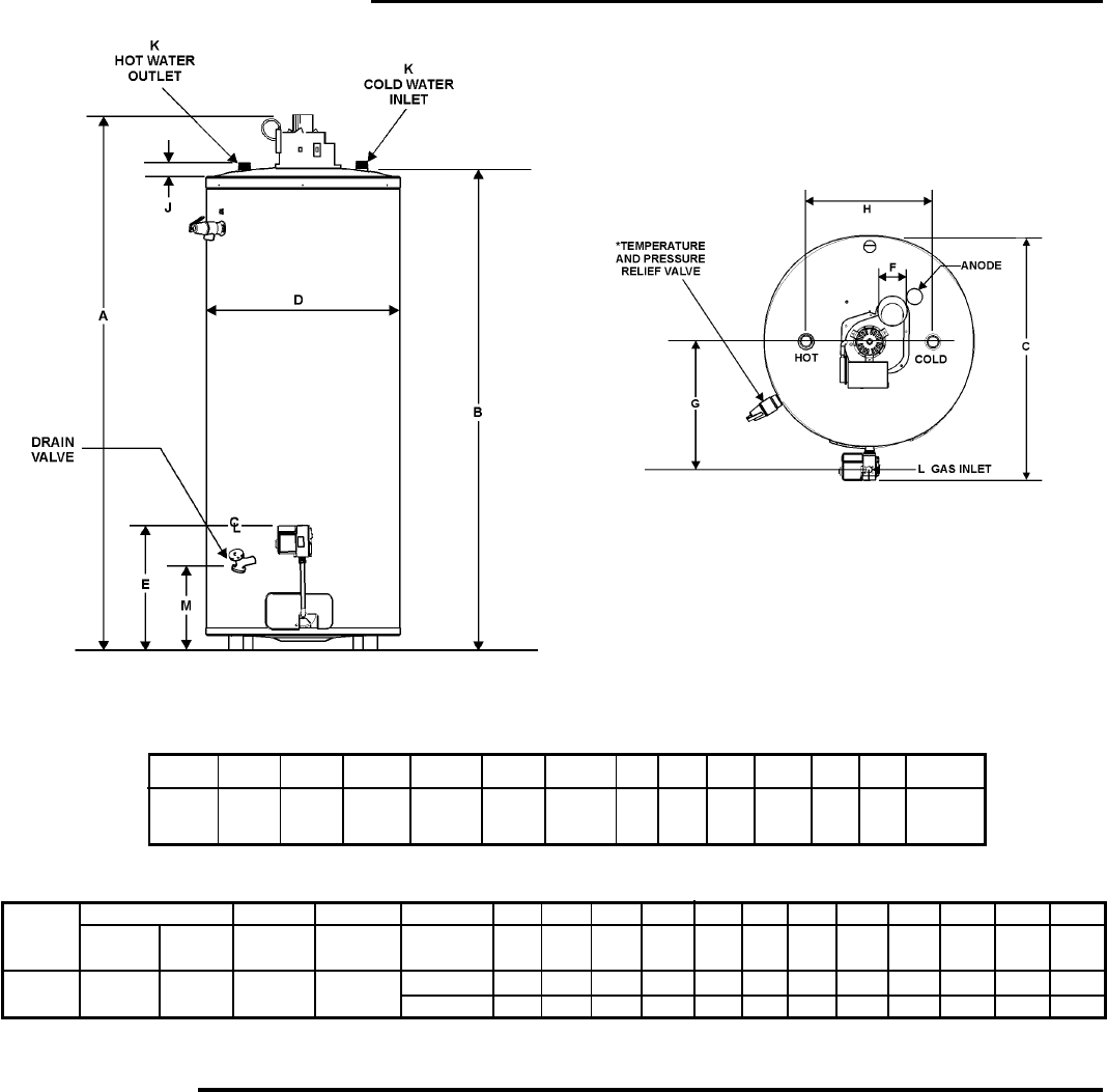
FIGURE 1
*INSTALL IN ACCORDANCE WITH LOCAL CODES
TOP VIEW
ALL DIMENSIONS IN INCHES
Model Units A B C D E F G H J K L M
BTF-75 Inches 66 5/16 58 1/2 29 5/8 25 3/8 15 3/16 4 14 16 1 1/4 1 1/2 11 15/16
cm 168.4 148.6 75.2 64.5 38.6 10.2 35.6 40.6 3.2 NPT NPT 30.3
RECOVERY CAPACITIES
Input Approx. Approx. Temp. °C 17 22 28 33 39 44 50 56 61 67 72 78
Model Rating Rating Gal. Liter
Btu/Hr KW/Hr Cap. Cap. Rise ° F 30 40 50 60 70 80 90 100 110 120 130 140
BTF-75 80,000 23.4 74 284 LPH 979 734 587 489 419 367 326 294 267 245 226 210
GPH 259 194 155 129 111 97 86 78 71 65 60 55
Recovery capacity based on 80% thermal efficiency.