


7
5. The vent termination shall not be mounted directly above or within 3
feet horizontally from an oil tank vent or gas meter to avoid potential
freeze-up from condensation.
Plan the vent system layout so that proper clearances are maintained
from plumbing and wiring.
Vent pipes serving power vented appliances are classified by building
codes as "vent connectors". Required clearances from combustible
materials must be provided in accordance with information in this manual
under LOCATION OF HEATER and VENT TERMINAL INSTALLATIONS,
and with the National Fuel Gas Code and local codes.
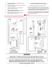
PLANNING THE VENT SYSTEM
Plan the route of the vent system from the discharge of the blower to
the planned location of the vent terminal.
1. Layout the total vent system to use a minimum of vent pipe and elbows.
Take into consideration that an elbow will be necessary to make the
first vent pipe connection to the power venter outlet (see Figure 6).
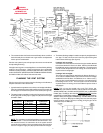
2. This water heater is capable of venting the flue gases the equivalent
of thirty (30) feet of 3 inch pipe or eighty-five (85) feet of 4 inch pipe
as listed in Table 1.
Number of 3" Maximum 4" Maximum
90° Elbows Pipe (Feet) Pipe Feet
ONE (1) 25 80
TWO (2) 20 75
THREE (3) 15 70
FOUR (4) 10 65
FIVE (5) - - - 60
TABLE 1
NOTE: The equivalent feet of pipe listed above are exclusive of the
"Tee" termination. That is, the first elbow and the termination "Tee",
with installed screens, are assumed to be in the system and the
remainder of the system must not exceed the thirty (30) equivalent
feet of 3 inch pipe or eighty five (85) equivalent feet of 4 inch pipe.
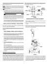
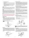
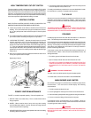
3. The blower discharge adapter is made to accept only straight sections
of 3" pipe. To start a minimum of 2 inches of 3" pipe must be glued
into the blower discharge (See figure 6).
If using 3 inch vent pipe:
A minimum of 2 inches, maximum of 4 feet of 3" pipe must be attached
to the blower before the first 3-inch elbow. After the first elbow add
the additional venting required for the installation. The total system
cannot exceed 30 equivalent feet of venting, where each elbow is
equal to 5 feet of straight pipe.
If using 4 inch vent pipe:
Two inches of 3" pipe must be attached to the blower discharge. A
4" x 3" reducer is added and then up to maximum 4 feet of 4 inch pipe
added before the first elbow. An additional 4" x 3" reducer and (1)
foot of 3" pipe must be added to the end of the vent system before
terminating into the 3" tee. The total system cannot exceed 85
equivalent feet of 4" venting, where each elbow is equal to 5 feet of
straight pipe.
NOTE: This unit can be vented using only PVC (Class 160,
ASTM D-2241; Schedule 40, ASTM D-1785; or Cellular Core Schedule
40 DWV, ASTM F-891), Schedule 40 CPVC/ASTM F-441), or ABS/ASTM
D-2661) pipe. The fittings, other than the
TERMINATION TEE should be
equivalent to PVC-DWV fittings meeting ASTM D-2665 (Use CPVC fittings,
ASTM F-438 for CPVC pipe and ABS fittings. ASTM D-2661/3311 for
ABS pipe. If CPVC or ABS pipe and fittings are used, then the proper
cement must be used for all joints, including joining the pipe to the
Termination Tee (PVC Material).
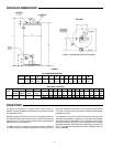
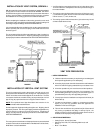
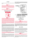
FIGURE 4
FIGURE 3
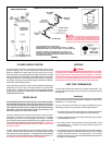
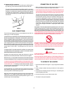
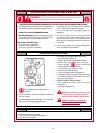
WARNING
VENT HOOD(S) MAY BE
EXTREMELY HOT
DURING OPERATION.