


10
INSTALLATION OF VENT SYSTEM, SIDEWALL
With the route of the venting system and selection of materials completed,
as discussed in section of this manual titled PLANNING THE VENT
SYSTEM, the through the wall vent terminal in place and the first section
of piping, up to first elbow, installed at the blower it is time to complete
the installation of the venting system for the sidewall installation.
Before completing the installation of the venting system be sure to read
the sections of this manual discussing the proper method of cutting and
cementing PVC pipe and fittings: VENT PIPE PREPARATION.
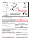
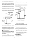
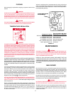
It is recommended that the completion of the venting system start at the
blower assembly and run to the coupling on the inside wall of the vent
terminal, Figure 5.
The vent system piping should be supported every 5 feet of vertical run
and every 3 feet of horizontal run. All piping and fittings must be joined
by the proper procedures as described under: VENT PIPE PREPARATION.
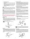
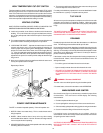
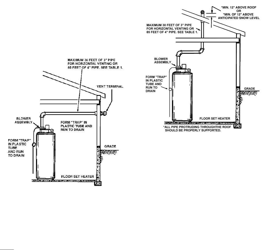
FIGURE 8
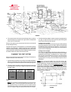
INSTALLATION OF VERTICAL VENT SYSTEM
This unit is approved for venting through the roof with only the vent
terminal that is included with the unit, see Figure 9. A proper flashing or
"BOOT" should be used to seal the pipe where it exits the roof. The total
vent system should not exceed the thirty (30) equivalent feet of 3 inch
pipe or sixty (60) equivalent feet of 4 inch pipe as listed in Table 1.
NOTE: The equivalent feet of pipe listed above are exclusive of the
"TEE" termination with installed screens.
Provide support for all pipe protruding through the roof. All piping should
be properly secured. The vent system piping should be supported every
5 feet of vertical run and every 3 feet of horizontal run. All piping and
fittings must be joined by the proper procedures as described under:
VENT PIPE PREPARATION.
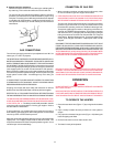
IMPORTANT
The vent system must terminate so that proper clearances are maintained
as cited in local codes or the latest edition of the National Fuel Gas Code,
ANSI Z223.1 and as listed below:
1. Vent Termination must extend a minimum of 12 inches above roof or
12 inches above the anticipated snow level to prevent blockage of
the vent termination.
2. The venting system shall terminate at least four (4) feet from or one
(1) foot above any gable, dormer or other roof structure with building
interior access; i.e., vent, window, etc.
3. The venting system shall terminate three (3) feet above any forced
air inlet located within ten feet.
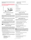
FIGURE 9
VENT PIPE PREPARATION
1. INITIAL PREPARATION
A. Make sure the solvent cement you are planning to use is designed
for the specific application you are attempting.
B. Know the physical and chemical characteristics and limitations
of the PVC and CPVC piping materials that you are about to use.
C. Know the reputation of your manufacturer and their products.
D. Know your own qualifications or those of your contractor. The
solvent welding technique of joining PVC and CPVC pipe is a
specialized skill just as any other pipe fitting technique.
E. Closely supervise the installation and inspect the finished job
before start-up.
F. Contact the manufacturer, supplier, or competent consulting
agency if you have any questions about the application or
installation of PVC and CPVC pipe.
G. Take the time and effort to do a professional job. Shortcuts will
only cause you problems and delays in start-up. By far, the
majority of failures in PVC and CPVC systems are the result of
shortcuts and/or improper joining techniques.
2. SELECTION OF MATERIALS
• Cutting Device - Saw or Pipe Cutter
• Deburring Tool, Knife, File, or Beveling Machine (2" and
above)
• Brush - Pure Bristle