


6
CLOSED WATER SYSTEM
A closed system will exist if a back-flow preventer (check valve),
pressure reducing valve, or other similar device is installed in the cold
water line between the water heater and the street main (or well).
Excessive pressure may develop due to the thermal expansion of heated
water causing premature tank failure or intermittent relief valve operation.
This type of failure is not covered by the limited warranty. An expansion
tank may be necessary in the cold water supply to alleviate this situation.
Contact the local plumbing authority.
If the temperature and pressure relief valve on the appliance discharges
periodically, this may be due to thermal expansion in a closed water
supply system. Contact the water supplier or local plumbing inspector
on how to correct situation. DO NOT PLUG THE TEMPERATURE AND
PRESSURE RELIEF VALVE.
RELIEF VALVE
A NEW TEMPERATURE AND PRESSURE RELIEF VALVE COMPLYING WITH
THE STANDARD FOR RELIEF VALVES AND AUTOMATIC GAS SHUT OFF
DEVICES FOR HOT WATER SUPPLY SYSTEMS, ANSI Z21.22 (LATEST
EDITION) MUST BE INSTALLED IN THE HEATER IN THE MARKED OPENING
PROVIDED. THE VALVE MUST BE OF A SIZE (INPUT RATING) THAT
WILL BE ADEQUATE FOR YOUR SIZE HEATER.
Check the metal tag on the relief valve and compare it to the heater’s
rating plate. The pressure rating of relief valve must not exceed the
working pressure shown on the rating plate of the heater. In addition
the hourly Btu rated temperature steam discharge capacity of the relief
valve shall not be less than the input rating of the heater. NO VALVE IS
TO BE PLACED BETWEEN THE RELIEF VALVE AND TANK. DO NOT PLUG
THE RELIEF VALVE.
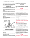
The drain line connected to this valve must not contain a reducing coupling
or other restriction and must terminate near a suitable drain to prevent
water damage during valve operation. The discharge line shall be installed
in a manner to allow complete drainage of both the valve and line. DO
NOT THREAD, PLUG OR CAP THE END OF THE DRAIN LINE.
VENTING
WARNING
THE INSTRUCTIONS IN THIS SECTION ON VENTING MUST BE FOLLOWED
TO AVOID CHOKED COMBUSTION OR RECIRCULATION OF FLUE GASES.
SUCH CONDITIONS CAUSE SOOTING OR RISKS OF FIRE AND
ASPHYXIATION. NEVER OPERATE THE HEATER UNLESS IT IS VENTED
TO THE OUTDOORS AND HAS ADEQUATE AIR SUPPLY TO AVOID RISKS
OF IMPROPER OPERATION, FIRE, EXPLOSION OR ASPHYXIATION.
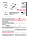
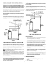
VENT PIPE TERMINATION
The first step is to determine where the vent pipe will terminate. The
vent may terminate through the roof (see Figure 9) or through a sidewall
(see Figure 8).
IMPORTANT
The vent system must terminate so that proper clearances are maintained
as cited in local codes or the latest edition of the National Fuel Gas Code,
ANSI Z223.1, 7.3.4e and 7.8a, b.
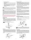
For your convenience instructions on proper installation through a
sidewall are provide in Figure 3 and the numbered points below:
1. The exit terminals of a mechanical vent system shall be not less than
7 feet above grade when located adjacent to public walkways.
2. A venting system shall terminate at least 3 feet above any forced air
inlet located within 10 feet.
3. The venting system shall terminate at least 4 feet below, 4 feet
horizontally from or, 1 foot above any door, window or gravity air
inlet into any building.
4. The manufacturer also recommends that the vent system termination
not be installed closer than 3 feet from an inside corner of an L shaped
structure and not be less than 1 foot above grade. The vent shall
terminate a minimum of 12'' above expected snowfall level to prevent
blockage of vent termination.
CAUTION: IF BUILDING COLD WATER SUPPLY HAS A BACK-FLOW
PREVENTER, CHECK VALVE OR WATER METER WITH CHECK VALVE,
PROVISIONS FOR THERMAL EXPANSION OF WATER IN THE HOT WATER
SYSTEM MUST BE PROVIDED.
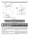
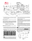
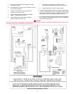
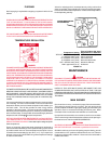
FIGURE 2
CIRCULATING RETURN LINE CONNECTIONS
TEMPERED WATER LOOP, IF USED, CONNECT TO POINT "A". STORED
TEMPERATURE WATER LOOP, IF USED, CONNECT TO COLD WATER INLET
WARNING
TEMPERATURE SETTING SHOULD NOT EXCEED SAFE USE
TEMPERATURE AT FIXTURES. SEE TEMPERATURE REGULATION
ON PAGE 9. IF HIGHER PREHEAT TEMPERATURES ARE
NECESSARY TO OBTAIN ADEQUATE BOOSTER OUTPUT, ADD AN
ANTI-SCALD VALVE FOR HOT WATER SUPPLIED TO FIXTURES.
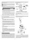
SINGLE TEMPERATURE
MIXING VALVE APPLICATION FOR TWO TEMPERATURE WATER