


8
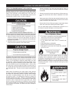
INSULATION BLANKETS
Insulation blankets available to the general public for external use
on gas water heaters are not necessary with this product. The
purpose of an insulation blanket is to reduce the standby heat
loss encountered with storage tank water heaters. Your Water
heater meets or exceeds the National Appliance Energy Conser-
vation Act standards with respect to insulation and standby loss
requirements, making an insulation blanket unnecessary.
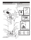
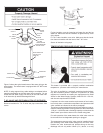
Should you choose to apply an insulation blanket to this heater,
you should follow these instructions (See Figure 1 for identifi ca-
tion of components mentioned below). Failure to follow these
instructions can restrict the air fl ow required for proper combus-
tion, resulting in fi re, asphyxiation, serious personal injury or
death.
• Do not cover the outer door, thermostat or temperature &
pressure relief valve.
• Do not cover the instruction manual. Keep it on the side of
the water heater or nearby for future reference.
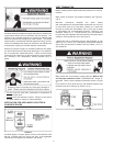
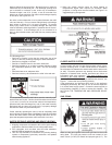
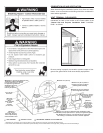
VENTILATION FOR APPLIANCES LOCATED IN
CONFINED SPACES
FIGURE 3
Confi ned Space is a space whose volume is less than 50 cubic
feet per 1,000 Btu per hour (4.8 cm per kW) of the aggregate
input rating of all appliances installed in that space.
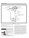
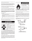
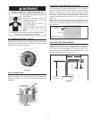
VENT TERMINATION
Before installing water heater determine placement of vent ter-
mination.
Make certain to observe vent location limitation, see Figures 3,
4 & 12.
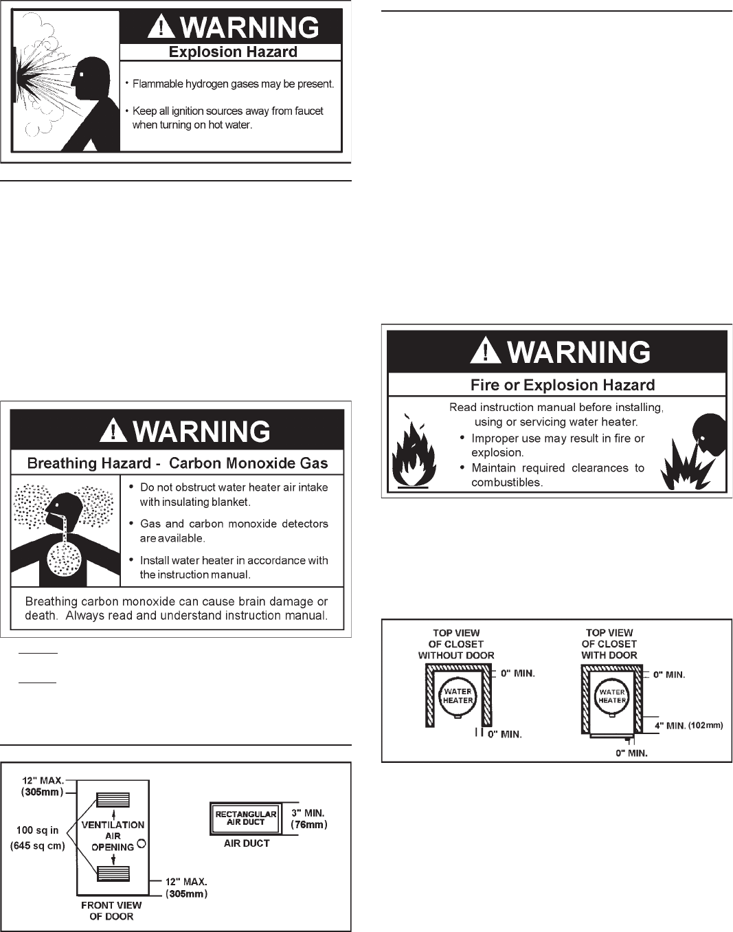
Minimum clearances between the water heater
and combustible and noncombustible construction are: 0mm (0
in.) from sides, 0mm (0 in.) from back, 102mm (4 in.) from front
of jacket to closet door and 508mm (20 in.) from top of jacket
to combustible and noncombustible material. Minimum vent
clearance: 25mm (1 in.)*. Provide 915mm (3 ft.) front clearance
for servicing and adequate clearance between the jacket top &
ceiling for servicing the fl ue area, see Figure 4.
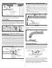
* Where the wall is combustible and the wall thickness is over
356mm (14 in.), 25mm (1 in.) clearance to combustible materials
around the vent terminal is needed. The fi rst 356mm (14 in.) is
zero clearance.
Make certain the vent locations comply with the “Natural Gas
and Propane Installation Code” CAN/CSA-B149.1 and/or lo-
cal codes. There is some important information shown in Figure
12.
For a second or more direct vent unit, the distance between vent
terminals must be a minimum of 305mm (12 in.).
FIGURE 4