


15
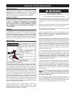
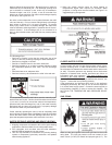
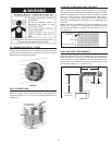
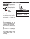
DV TERMINATION SAFETY COVER
A Safey cover (see Figure 13) is available to prevent accidental
contact with the vent terminal. Contact your Customer Service
Department for ordering information.
FIGURE 13
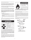
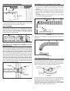
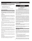
VENT CONNECTIONS
After the location for the vent terminal has been selected as
outlined in Figures 3, 4 & 12, use the following illustrations for
installation:
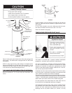
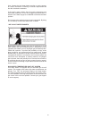
FIGURE 14
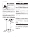
LOCATING CLEARANCE HOLE FOR VENT
Cut a clearance hole, approximately 178mm (7 in.) in diameter,
through the exterior wall for the vent assembly. The recommended
distance, measured from the hole center to bottom of water
heater, is 1.72m (68 in.) for 40 gal. models and 1.93m (76 in.)
for 50 gal., 50 gal. Hi-Input and 75 gal. models. The maximum
distance recommended is 2.03m (80 in.) or in compliance with
Figure 16.
Where the wall is combustible and the wall thickness is over
356mm (14 in.), 25mm (1 in.) clearance to combustible materials
around the vent terminal is needed. The fi rst 356mm (14 in.) is
zero clearance.
7 in. (178mm )
DIAMETER
BOTTOM OF HEATER
(SEE TEXT)
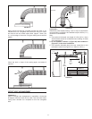
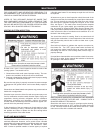
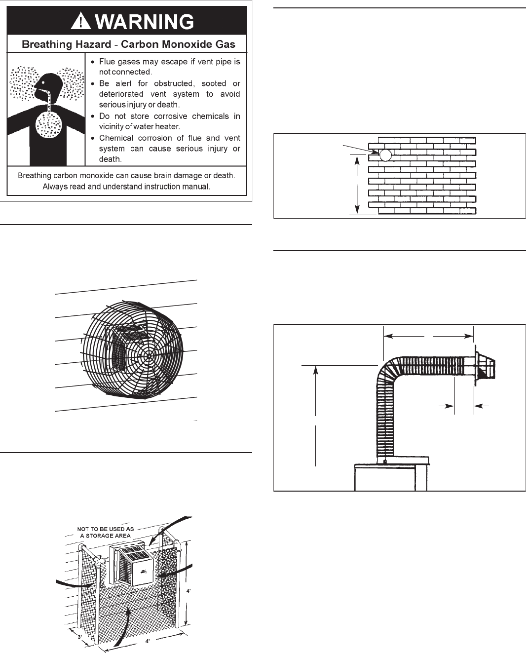
FIGURE 15
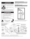
HIGH RISE VENT ARRANGEMENT
When the height H (From vent terminal center line to bottom of
heater) is over 80 in. (2.03m), it is a high rise vent arrangement.
In this case the minimum distance “D” from the center of the
water heater to the outside wall surface is 560mm (22 in.), and
the maximum height of “H” is 3.66m (12 ft.).
TO BOTTOM
OF HEATER
WALL THICKNESS
10 in.
(254mm)
(REF)
D
H
FIGURE 16