11
distance below the structural fl oor. Be certain that no contact is
made with any live electrical part. The discharge opening must
not be blocked or reduced in size under any circumstances.
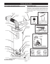
Excessive length, over 30 ft. (9.14m), or use of more than four
elbows can cause restriction and reduce the discharge capacity
of the valve, see Figures 5 or 10.
No valve or other obstruction is to be placed between the relief
valve and the tank. Do not connect tubing directly to discharge
drain unless a 152mm (6 in.) air gap is provided. To prevent
bodily injury, hazard to life, or property damage, the relief valve
must be allowed to discharge water in quantities should circum-
stances demand. If the discharge pipe is not connected to a
drain or other suitable means, the water fl ow may cause property
damage.
The Discharge Pipe:
• Shall not be smaller in size than the outlet pipe size of the
valve, or have any reducing couplings or other restrictions.
• Shall not be plugged or blocked.
• Shall be of material listed for hot water distribution.
• Shall be installed so as to allow complete drainage of both
the temperature-pressure relief valve, and the discharge
pipe.
• Shall terminate at an adequate drain.
• Shall not have any valve between the relief valve and tank.
The temperature-pressure relief valve must be manually oper-
ated at least once a year. Caution should be taken to ensure that
(1) no one is in front of or around the outlet of the temperature-
pressure relief valve discharge line, and (2) the water manually
discharged will not cause any bodily injury or property damage
because the water may be extremely hot.
If after manually operating the valve, it fails to completely reset
and continues to release water, immediately close the cold water
inlet to the water heater, follow the draining instructions, and re-
place the temperature-pressure relief valve with a new one.
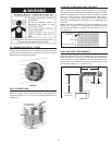
WATER (POTABLE) HEATING AND SPACE HEATING
1. All piping components connected to this unit for space heating
applications shall be suitable for use with potable water.
2. Toxic chemicals, such as those used for boiler treatment,
shall NEVER be introduced into this system.
3. This unit may NEVER be connected to any existing heating
system or component(s) previously used with a non-potable
water heating appliance.
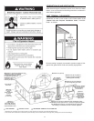
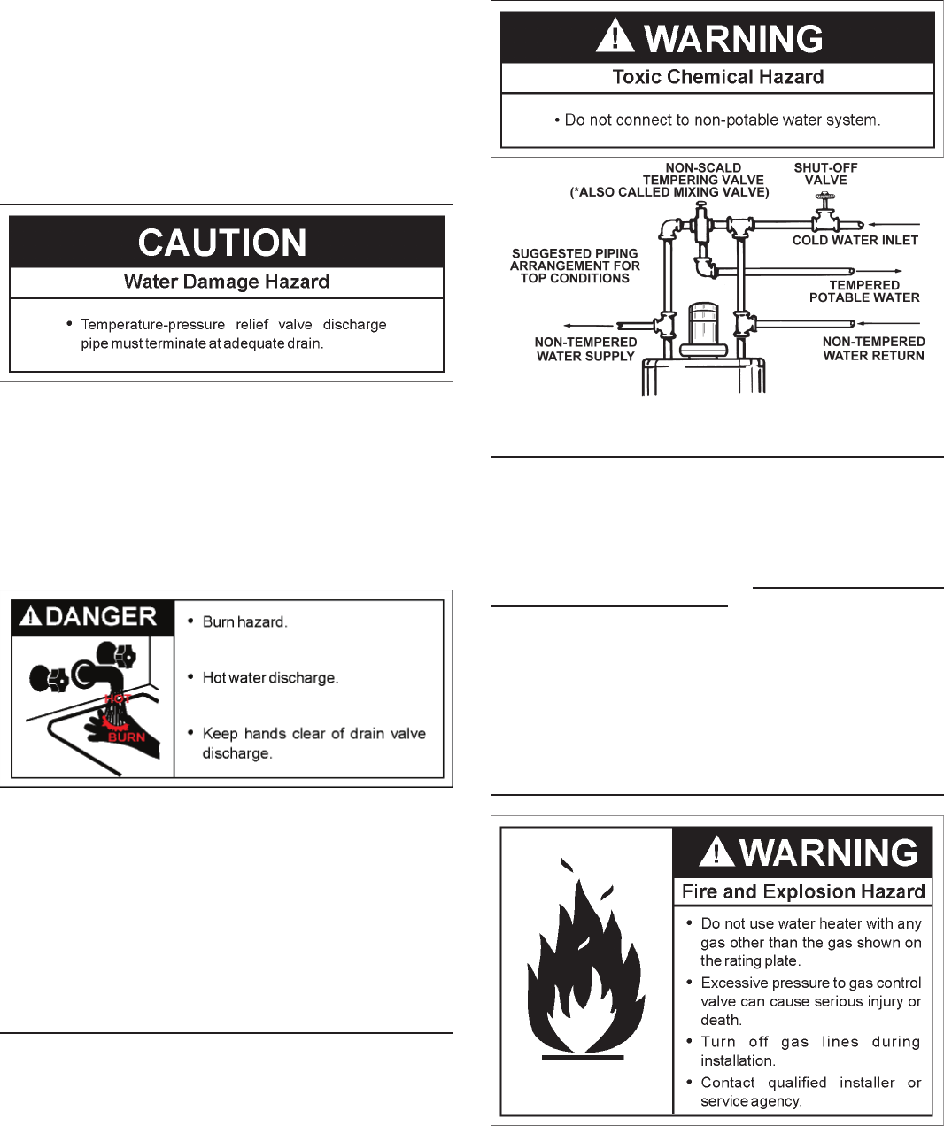
4. When the system requires water for space heating at
temperatures higher than required for domestic water
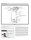
purposes, a *mixing valve must be installed, see Figure 7 for
suggested piping arrangement.
FIGURE 7
CLOSED WATER SYSTEM
A closed system will exist if a back-fl ow preventer (check valve),
pressure reducing valve, or other similar device is installed in
the cold water line between the water heater and the street main
(or well). Excessive pressure may develop due to the thermal
expansion of heated water causing premature tank failure or
intermittent relief valve operation. This type of failure is not
covered by the limited warranty. An expansion tank may be
necessary in the cold water supply to alleviate this situation, see
Figure 1. Contact the local plumbing authority.
If the temperature and pressure relief valve on the appliance
discharges periodically, this may be due to thermal expansion
in a closed water supply system. Contact the water supplier or
local plumbing inspector on how to correct this situation. DO
NOT PLUG THE TEMPERATURE AND PRESSURE RELIEF
VALVE.
GAS PIPING
Make sure the gas supplied is the same type listed on the model
rating plate. The inlet gas pressure must not exceed 14 inch
water column (3.5 kPa) for natural and propane gas (L.P.). The


