


12
minimum inlet gas pressure shown on the rating plate is that
which will permit fi ring at rated input.
All gas piping must comply with local codes and ordinances or
with the “Natural Gas and Propane Installation Code” CAN/
CSA-B149.1 whichever applies. Copper and brass tubing and
fi ttings (except tin lined copper tubing) shall not be used.
If the gas control valve is subjected to pressures exceeding 1/2
psi (3.5 kPa), the damage to the gas control valve could result in
a fi re or explosion from leaking gas.
If the main gas line Shut-off serving all gas appliances is used,
also turn “off” the gas at each appliance. Leave all gas appli-
ances shut “off” until the water heater installation is complete.
A gas line of suffi cient size must be run to the water heater.
Consult the current edition of “Natural Gas and Propane
Installation Code” CAN/CSA-B149.1 and your gas supplier
concerning pipe size.
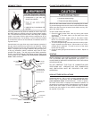
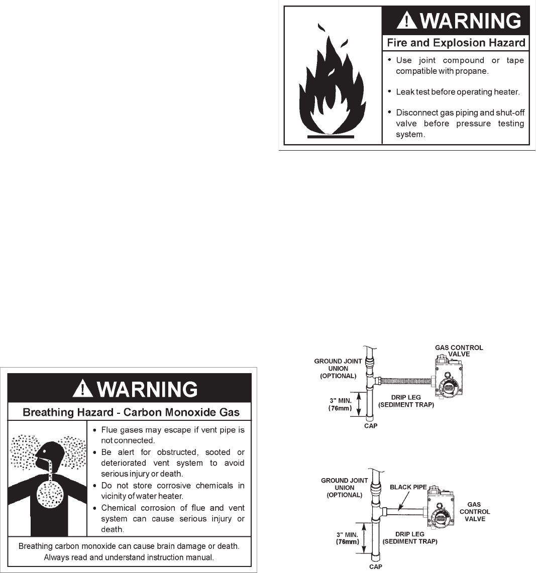
There must be:
• A readily accessible manual shut off valve in the gas supply
line serving the water heater, and
• A drip leg (sediment trap) ahead of the gas control valve to
help prevent dirt and foreign materials from entering the gas
control valve.
• A fl exible gas connector or a ground joint union between the
shut off valve and control valve to permit servicing of the
unit.
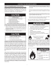
Be sure to check all the gas piping for leaks before lighting the
water heater. Use a soapy water solution, not a match or open
fl ame. Rinse off soapy solution and wipe dry.
When installed at elevations above 7,700 feet (2,347 meters), input
rating should be reduced at the rate of 4 percent for each 1,000 feet
(305 meters) above sea level which requires replacement of the
burner orifi ce in accordance with “Natural Gas and Propane
Installation Code” CAN/CSA-B149.1. Contact your local gas
supplier for further information.
Failure to replace the standard orifi ce with a high altitude orifi ce
when installed could result in improper and ineffi cient operation
of the appliance, producing carbon monoxide gas in excess of
safe limits, which could result in serious injury or death. Contact
your gas supplier for any specifi c changes which may be re-
quired in your area.
Use pipe joint compound or tefl on tape marked as being resis-
tant to the action of petroleum [Propane (L.P.)] gases.
The appliance and its gas connection must be leak tested before
placing the appliance in operation.
The appliance and its individual Shut-off valve shall be discon-
nected from the gas supply piping system during any pressure
testing of that system at test pressures in excess of 1/2 pound
per square inch (3.5 kPa). It shall be isolated from the gas sup-
ply piping system by closing its individual manual Shut-off valve
during any pressure testing of the gas supply piping system at
test pressures equal to or less than 1/2 pound per square inch
(3.5 kPa).
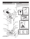
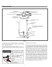
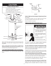
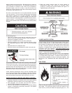
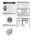
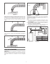
Connecting the gas piping to the gas control valve of the water
heater can be accomplished by either of the two methods shown
in Figures 8 and 9.
FIGURE 8 GAS PIPING WITH
FLEXIBLE CONNECTOR.
FIGURE 9 GAS PIPING WITH ALL
BLACK IRON PIPE TO GAS CONTROL.