


14
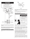
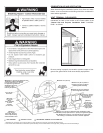
COMBUSTION AIR AND VENTILATION
When determining the installation location for a direct vent water
heater, snow accumulation and drifting should be considered in
areas where applicable.
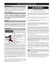
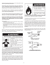
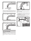
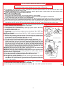
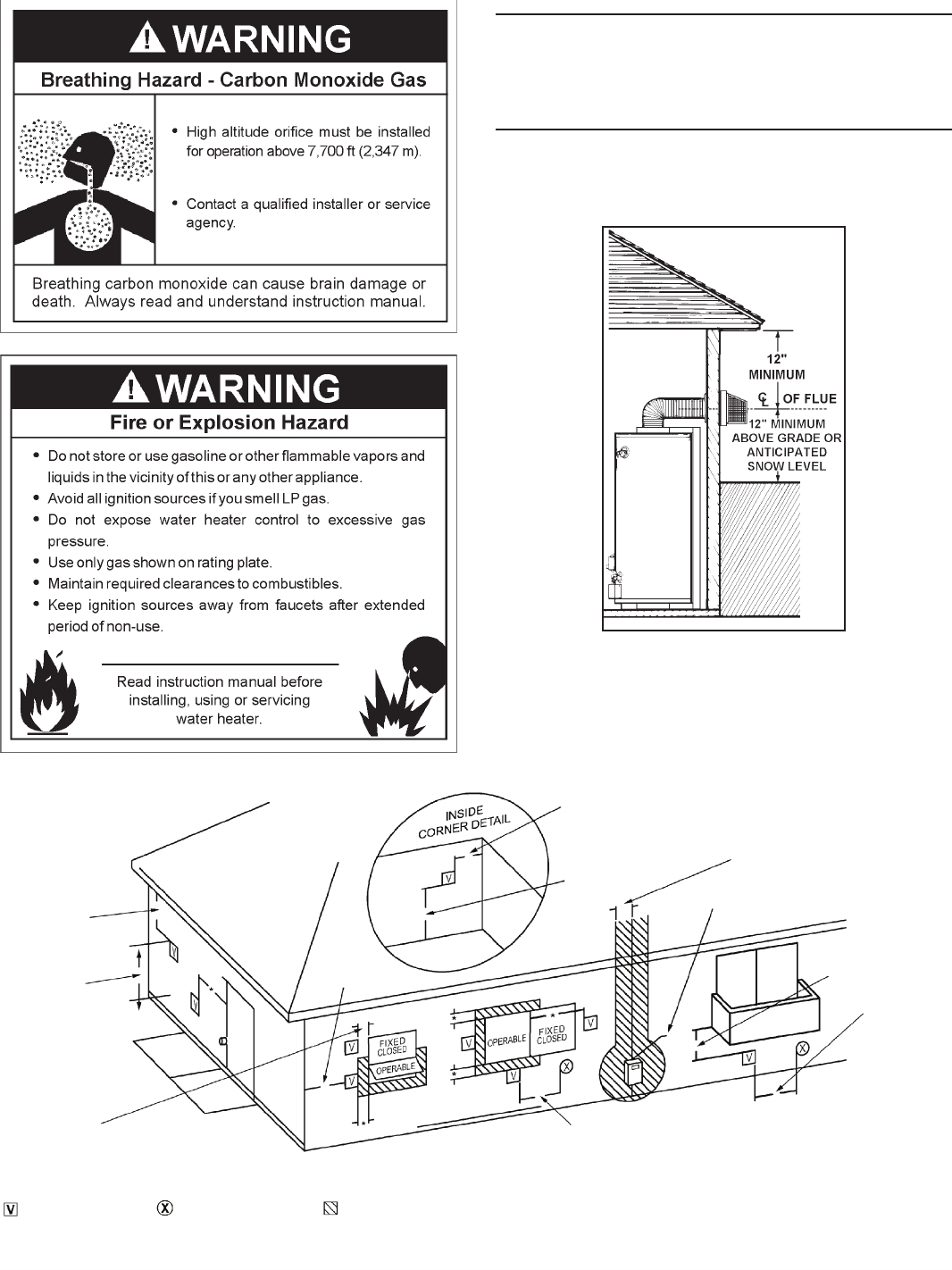
VENT TERMINAL CLEARANCES
The vent system must terminate so that proper clearances are
maintained as cited in local codes or the current edition of the
“Natural Gas and Propane Installation Code” CAN/CSA-
B149.1 as follows:
FIGURE 11
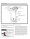
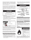
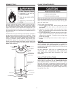
Be sure venting is properly connected to prevent escape of dan-
gerous fl ue gases which could cause deadly asphyxiation.
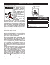
FIGURE 12
*
*
*
*
*
Minimum 18 in. (46 cm)
12 in. (30 cm)
above grade or
anticipated snow
level
Minimum 3 ft. (91 cm) within a
height of 15 ft. (4.6 cm) above
meter/regulator assembly
Minimum 3 ft. (91 cm) clearance
to service regulator vent outlet
Minimum 12 in. (30 cm)
under veranda, porch,
deck or balcony
(see footnote 1)
Minimum
3 ft. (91 cm)
above if within
10 ft. (3 m)
horizontally to
a mechanical air
supply inlet
Minimum
12 in. (30 cm)
from sides, above or
below a permanently
closed window or door
Minimum
7 ft. (2.3 m)
above
public sidewalk
or paved
driveway
(see footnote 2)
Minimum 9 in. (23 cm) for appliances with 10,000 btuh (3 Kw)
to 50,000 btuh (15 Kw) inputs and 12 in. (30 cm) for appliances greater
than 50,000 btuh (15 Kw) to a non mechanical air supply inlet
into building or combustion air inlet to another appliance
12 in. (30 cm)
from soffit
*Minimum 9 in. (23 cm) for appliances with
10,000 btuh (3 Kw) to 50,000 btuh
(15 Kw) inputs and 12 in. (30 cm)
for appliances greater than
50,000 btuh (15 Kw) to
a window or door
that may be opened
Minimum
2 ft. (61 cm)
from outside
corner
1. Permitted only if veranda, porch, deck or balcony is fully opened on a minimum of two sides beneath the floor.
2. A vent shall not terminate above a sidewalk or paved driveway that is located between two single family dwellings and serves both dwellings.
AREA WHERE TERMINAL IS NOT PERMITTED
VENT TERMINAL AIR SUPPLY INLET