


9
Blower Speed
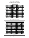
For optimum system performance and comfort,
it may be necessary to change the factory speed
setting. See Table 4 (page 20) for factory settings.
NOTE: Q5RF models have High Effi ciency Motors
with 5 speed taps.
WARNING:
To avoid electric shock, personal
injury, or death, turn off the electric
power at the disconnect or the main
service panel before making any
electrical connections.
1. Disconnect all electrical power to the unit and
remove the service panel.
CAUTION:
Label all wires prior to disconnection
when servicing controls. Wiring
errors can cause improper and
dangerous operation. Verify proper
operation after servicing.
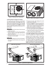
2. Locate the orange, black and red wires
terminated to the blower motor. The orange
wire controls the low speed cooling and heating
operations, the black wire controls high speed
cooling and heating operations and the red
wire controls the electric heating operation.
Overcurrent Protection
Overcurrent protection must be provided at the
branch circuit distribution panel and sized as
shown on the unit rating label and according to
applicable local codes. Generally, the best fuse
or breaker for any heat pump is the smallest
size that will permit the equipment to run under
normal usage and provide maximum equipment
protection. Properly sized fuses and breakers
also prevent nuisance trips during unit startup.
If a fuse blows or a breaker trips, always
determine the reason. Do not arbitrarily install
a larger fuse or breaker and do not, in any
case, exceed the maximum size listed on the
data label of the unit.
2-Speed Outdoor Fan Motor
(Select Models)
If the unit utilizes a 2-speed condenser fan motor,
this motor will operate on low speed when in low
cooling/heating, and on high speed when in high
cooling/heating.
CAUTION:
To avoid personal injury or
property damage, make certain
that the motor leads cannot
come into contact with any metal
components of the unit.
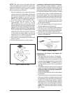
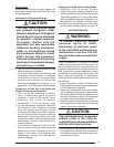
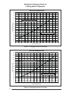
3. Verify the required speed from the airfl ow data
found in Table 4. Place appropriate wire on the
appropriate motor speed tap for the required
airfl ow.
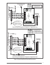
4. Check all factory wiring per the unit wiring
diagram and inspect the factory wiring
connections to be sure none loosened during
shipping or installation.
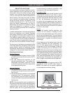
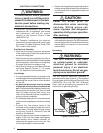
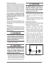
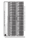
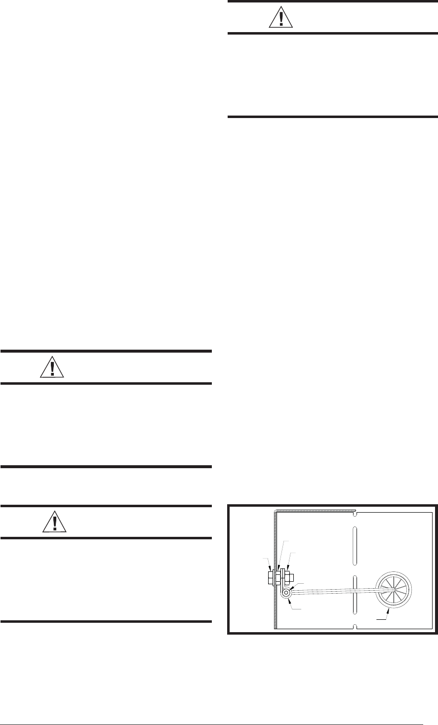
Ambient Sensor Mounting
For optimum performance of the heat pump
system, the ambient sensor (Figure 9) must be
mounted on the outside of the unit.
1. Remove the mounting bracket and all
hardware included in the packet.
2. Remove star bushing from 7/8”
hole in corner panel of the unit.
3. Route the ambient sensor through the 7/8”
hole in the corner panel of the unit, and then
through the 7/8” hole in the mounting bracket.
4. Route the sensor through the
star bushing. Use the star bushing to
secure the mounting bracket to the unit.
5. Secure the ambient sensor inside the
plastic clip and secure it to the mounting
bracket with the screw and nut provided.
6. Install one spacer next between the
plastic clip and mounting bracket.
7. Bend the mounting bracket into position.
Install the mounting bracket to the unit
using the screw in the corner panel.
Star Bushing
Bolt
Nut
Ambient Sensor
Plastic Clip
Nut
Figure 9. Ambient Sensor Mounting