


2
Safety Information ........................................4
General Information .....................................4
Before You Install this Unit ..........................4
Locating the Heat pump ............................4
Air Duct System .........................................5
Unconditioned Spaces .............................5
Condensate Drainage .................................5
Heat Pump Installation .................................5
Unpacking the Unit ....................................5
Minimum Clearances .................................5
Service Access Clearance ......................5
Clearances to Combustibles ...................5
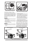
Installing Return & Supply Air Fittings ........6
Return Duct .............................................6
Supply Duct ............................................6
Locating & Installing the Return Air
Assembly ....................................................6
Locating & Installing the Supply
Dampers .................................................... 7
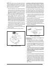
Connecting the Return & Supply Air
Flexible Ducts .............................................7
Electrical Connections .................................8
Pre - Electrical Checklist.............................8
Line Voltage ................................................8
Grounding ...................................................8
Overcurrent Protection ...............................9
2 - Speed Outdoor Fan Motor .....................9
Blower Speed ............................................9
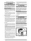
Ambient Sensor Mounting ..........................9
Demand Defrost Control ...........................11
Electric Heat Package ..............................11
Thermostat Connections ..........................11
Startup & Adjustments...............................12
Pre - Start Checklist .................................12
Start - Up Procedure ................................12
Air Circulation ........................................12
System Heating .....................................12
System Cooling ......................................12
Short Cycle Protection ...........................12
Emergency Heat ....................................12
Forced Defrost Mode (Field Test) .............12
Anti Short Cycle Timer Test ......................12
Heating Mode ........................................12
Cooling Mode .........................................13
Adjustment of Refrigerant Charge ............13
Charging an R410A Unit in AC
Mode with Outdoor Temp above 65° F .....13
Charging an R410A Unit in Heat Mode ....13
Unit Maintenance ........................................13
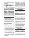
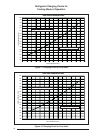
Refrigerant Charging Charts for
Cooling Mode of Operation .......................14
Figure 11 - 2 Ton Units .............................14
Figure 12 - 3 Ton Units .............................14
Figure 13 - 4 Ton Units .............................15
Figure 14 - 5 Ton Units .............................15
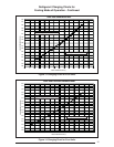
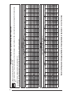
Refrigerant Charging Tables for Heating
Mode of Operation ......................................16
Table 2 - Chart for 2 & 3 Ton Units ............16
Table 3 - Chart for 4 & 5 Ton Units ............17
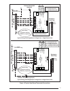
Wiring Diagrams .........................................18
Figure 15 - 2 & 3 Ton Units .......................18
Figure 16 - 4 & 5 Ton Units .......................19
Component Functions ...............................20
Low Pressure Switch ................................20
High Pressure Switch ...............................20
USER INFORMATION
INSTALLER INFORMATION
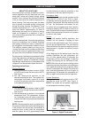
About the Heat Pump ...................................3
Operating Instructions ................................3
Cooling Operation ....................................3
Heating Operation ....................................3
Emergency Heat ......................................3
Defrost .....................................................3
System Shutdown ....................................3
Warranty Information
A warranty certificate with full details is
included with the heat pump. Carefully review
these responsibilities with your dealer or
service company. The manufacturer will not be
responsible for any costs found necessary to
correct problems due to improper setup, improper
installation, adjustments, improper operating
procedure on the part of the user, etc. Some
specifi c examples of service calls which are not
included in the limited warranty are:
1. Correcting wiring problems in the electrical
circuit supplying the heat pump.
2. Resetting circuit breakers or other switches.
3. Adjusting or calibrating of thermostat.
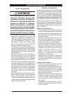
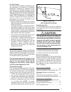
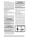
IMPORTANT SAFETY INFORMATION
Safety markings are used frequently throughout
this manual to designate a degree or level
of seriousness and should not be ignored.
WARNING indicates a potentially hazardous
situation that if not avoided, could result in
personal injury or death. CAUTION indicates
a potentially hazardous situation that if not
avoided, may result in minor or moderate injury
or property damage.