


6
2. Overlap the collar ends keeping the small
screw holes underneath.
3. Align the holes in the crimped area and install
one screw. NOTE: It may be necessary to
loosen the four screws that hold the transition
duct in order to install the supply fi tting. Re-
tighten when installation is complete.
4. Tap collar (if necessary) to ensure engagement
with unit opening and install second screw.
5. Tighten fi rst screw and rotate collar clockwise
so joint is near three o’clock position.
Locating & Installing the Return Air Assembly
To simplify installation, locate and install the
return air assembly fi rst. If desired, the return
opening can be located inside a closet with
louvered doors that has an open area equal
to or greater than the 12” x 20” grille furnished.
The return air grille can be placed in the wall
of a closet and the air ducted into the fi lter box
through a boxed-in area at the closet fl oor level.
Make sure the fi lter is readily accessible.
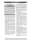
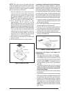
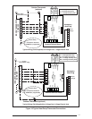
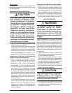
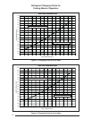
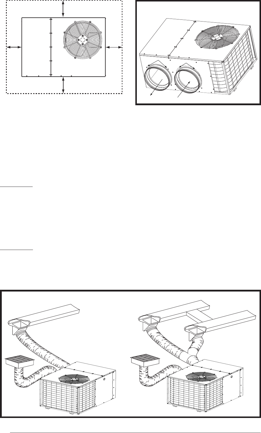
MULTIPLE DUCT APPLICATIONSINGLE DUCT APPLICATION
Figure 5. Typical Duct Applications
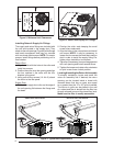
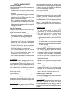
Figure 4. Return and Supply Air Fittings
Supply Air
14” Duct Dimples
Return Air
Transition Duct Screws
Installing Return & Supply Air Fittings
The supply and return fi ttings are included with
the unit and located in the supply duct. They
attach to the unit openings (Figure 4) with a fl ange
and bead arrangement and may be, secured
with two sheet metal screws. NOTE: For easier
access, install fi ttings before positioning unit in
fi nal location.
Return Duct
1. Align the slots with the holes in the collar and
install two screws.
2. Position the collar over the opening and align
the four notches in the collar with the four
dimples in the panel.
3. Using self-drilling screws (10-16x.5) attach
the collar to the rear panel.
Supply Duct
1. Position the supply duct collar so the edge of
the unit opening fi ts between the fl ange and
the bead.
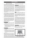
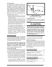
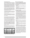
Figure 3. Minimum Unit Clearances
12"
12"
24"
TOP OF UNIT
TO BE
UNOBSTRUCTED
0"