


5
HEAT PUMP INSTALLATION
Unpacking the Unit
It is recommended that the unit be unpacked
at the installation site to minimize damage due
to handling.
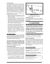
CAUTION:
Do not tip the unit on its side. Oil
may enter the compressor cylinders
and cause starting trouble. If unit has
been set on its side, restore to upright
position and do not run for several
hours. Then run unit for a few seconds.
Do this three or four times with fi ve
minutes between runs.
1. Remove the bands from around the unit.
2. Unfold the top and bottom cap fl anges.
3. Carefully remove the top cap and tube.
Minimum Clearances
Minimum clearances MUST be maintained from
adjacent structures to provide room for proper
servicing and air circulation. DO NOT install unit
in a confi ned or recessed area that will allow
discharge air from the unit to re-circulate into
the condenser air inlet, through the coil. See
Figure 3 (page 6).
Service Access Clearance:
Blower access panel side .......................... 24”
Electrical compartment access panel side ...12”
Clearance between overhang and
top of unit ...............................................72”
Clearance around condenser coil area to
wall or shrubs (excludes duct panel side) .. 12”
Clearances to Combustibles:
Combustible Base (Wood or Class A, B, or C
roof Covering material) ...............................0”
Supply and Return Air Ducts .......................0”
Duct Connection side ..................................0”
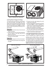
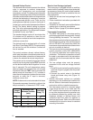
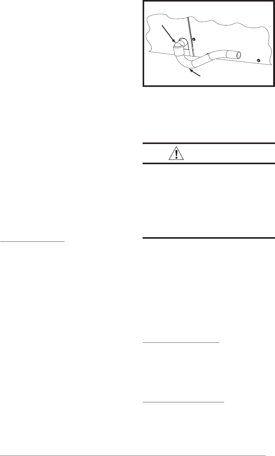
Elbow
Figure 2. Drain Trap
P-Trap
Condensate Drainage
A 3/4” condensate fi tting extends out of the side
of the unit (Figure 2). The drain trap, shipped in
the electrical compartment, must be installed
to prevent water from collecting inside the unit.
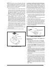
1. Thread the elbow provided with the unit
into the drain connection until hand tight.
2. Connect the condensate tubing onto the fi tting,
forming a trap near the drain connection.
3. Route the condensate tube from the trap
to a suitable drain. NOTE: For proper
drainage, make sure the trap is level to the
ground and tubing outlet is below trap level.
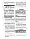
Air Duct System
Air ducts must be installed in accordance with
the standards of the National Fire Protection
Association “Standard for Installation of Air
Conditioning and Ventilation Systems” (NFPA
90A), “Standard for Installation of Residence Type
Warm Air Heating and Air Conditioning Systems”
(NFPA 90B), these instructions, and all applicable
codes. NFPA publications are avaialable by
writing to: National Fire Protection Association,
Batterymarch Park, Quincy, ME 02269 or visit
www.NFPA.org on the web.
• Design the duct work according to methods
described by the Air Conditioning Contractors
of America (ACCA).
• The supply duct system, including the number
and type of registers, will have much more
effect on the performance of the system than
any other factor. The duct must be suffi ciently
large to conduct an adequate amount of air to
each register. See Figure 4 (page 6).
• Duct work should be attached directly to the
unit fl anges for horizontal applications.
• If roof curb is installed, the ducts must be
attached to the curb hangers, not the unit.
• For highly resistive duct systems it may be
necessary to add an additional return air
duct and or supply to achieve maximum
performance and prevent coil icing and
refrigerant fl ood back
Unconditioned Spaces
All duct work passing through unconditioned
space must be properly insulated to minimize duct
losses and prevent condensation. Use insulation
with an outer vapor barrier. Refer to local codes
for insulation material requirements.
The heat pump system will not cool or heat
the home if air is lost to the outside through
leaks in the duct system. Ducts that are
collapsed or restricted by foreign objects
will also prevent adequate air fl ow.