


12
STARTUP & ADJUSTMENTS
Pre-Start Checklist
The following check list should be observed prior
to starting the unit.
Is the unit level? Unit should be level or slightly
slanted toward the drain for proper condensate
drainage.
Is the unit installed with the proper clearances
as listed in Figure 3 (page 6)?
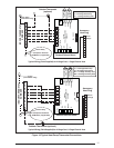
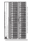
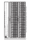
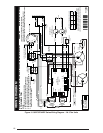
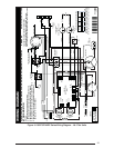
Is the wiring correct according to the wiring
diagram and electrical codes?
Are all the wiring connections tight? Check
the condenser fan to make sure it turns freely.
Is the overcurrent protection properly sized?
Is the thermostat wired correctly? Is it installed
in a proper location?
Start-Up Procedure
The control circuit consists of an anti-short cycle
timer that will not let the compressor re-start
before 5 minutes have elapsed.
1. Set the system mode to OFF and the
temperature mode to its highest setting.
2. Turn power on at the disconnect switch.
3. Set the system mode to ON or COOL.
4. Set the temperature mode below room
temperature. Verify that the indoor blower,
outdoor fan, and compressor energize and
the cooling function starts.
5. Verify the discharge air grilles are adjusted
and the system air is balanced.
6. Verify the duct work has no air leaks.
7. Verify the condensate drain is installed
correctly and functions properly.
8. Set the temperature mode above room
temperature. The unit should stop.
9. Instruct the homeowner on unit and thermostat
operation and fi lter servicing.
Air Circulation
Leave the thermostat system mode on OFF,
and set the fan mode to ON. Blower should
run continuously. Check the air delivery at the
supply registers and adjust register openings for
balanced air distribution. Examine ductwork for
leaks or obstruction if insuffi cient air is detected.
Set the thermostat fan mode to AUTO. The blower
should stop running.
System Heating
Set the thermostat system mode to HEAT and
the fan mode to AUTO. Change the thermostat
temperature selector above the existing room
temperature and check for the discharge of warm
air at the supply registers.
System Cooling
Set the thermostat’s system mode to COOL and
the fan mode to AUTO. Change the thermostat
temperature selector below the existing room
temperature. Allow the cooling system to operate
for several minutes and check for the discharge
of cool air at the supply registers.
Short Cycle Protection
The control circuit is equipped with a time-delay
feature for protection against short cycling.
With the system operating in the cooling mode,
gradually raise the thermostat temperature
setting until the whole system de-energizes.
Immediately lower the thermostat temperature
to the original setting and verify that the indoor
blower is energized. After approximately 5
minutes the compressor and the outdoor fan
will energize.
Emergency Heat
1. Set the thermostat’s system mode to EM
HT and the fan mode to either AUTO
(intermittent air) or to ON (continuous air).
2. Set the thermostat’s temperature
selector above the existing room
temperature and check the following:
• The thermostat auxiliary heat light (RED) is
on.
• The AC compressor and the fan should not
run; low voltage circuit remains energized.
• The blower runs according to the thermostat’s
fan mode setting.
Forced Defrost Mode (Field Test)
• When the TEST terminals are shorted with
the Y input active and pressure switches
closed, the ACSD will be eliminated and the
compressor contactor output energizes within
2 seconds. When the TEST terminals are
shorted for more than 9 seconds with the Y
input active, the control will be placed into a
forced defrost mode.
NOTE: The coil temperature sensor does not
need to be cold when the unit is forced into
defrost.
• After the TEST input is removed, the defrost
mode will terminate in 13.7 minutes or less
or when the coil temperature is above the
terminate set point or when the thermostat Y
input is removed, whichever occurs fi rst.
Anti Short Cycle Timer Test
The 5 minute time delay feature can be bypassed
by shorting the TEST pins together.
Heating Mode
When the TEST pins are shorted together for
more than 1 second, the control will switch
between defrost mode and heating mode as
described in the Forced Defrost Mode procedure
section.