


7
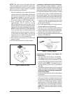
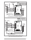
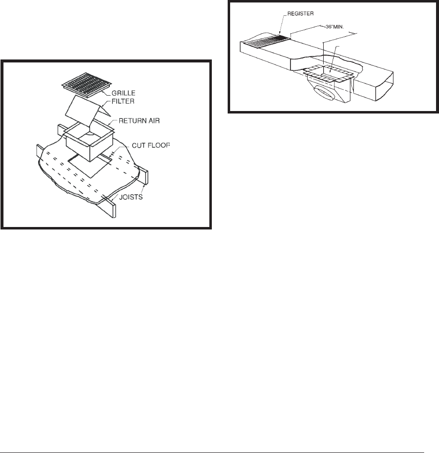
Figure 7. Supply Damper
AUTOMATIC DAMPER IS CLOSED
WHEN HEAT PUMP IS OFF
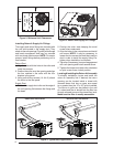
Figure 6. Return Air Box
NOTE: The return air box with grille and fi lter
(Figure 6) should not be located in heavy traffi c
areas like hallways or center of rooms. A good
spot is in a corner or under a table, if a minimum
two inch clearance is available.
1. Start the installation from under the home by
cutting a small hole in the subfl oor. Determine
how the fl oor joist location will affect cutting
the opening needed for the return air box.
NOTE: Floor joists are generally located on
16” centers, leaving 14-3/8” between joists.
2. After measuring the return air box
(approximately 12-1/4” x 20-1/4”), cut the
hole through the fl oor so that the box will fi t
between the fl oor joists. Care should be taken
when cutting through carpeting to avoid snags.
NOTE: In most installations it will be necessary
to cut a similar hole in the fi berboard directly
under the hole in the fl oor. However, if the fl oor
is more than ten inches deep, it will only be
necessary to cut a hole for the collar on the
return air box or for the insulated duct.
3. Set the box into the opening and fasten with
screws or nails.
4. Put the fi lter and return air grille in place.
Locating & Installing the Supply Damper(s)
When locating the supply damper(s), carefully
check fl oor joists and frame members that could
interfere with the installation of the damper or
fl exible duct. Ideally, the damper (Figure 7) should
be located in the bottom of the main duct, forward
of center of the home, at least three feet from
the nearest register. The round supply opening
in the slanted side of the damper should face the
side of the home where the heat pump is located.
1. Locate the center of the heat duct by cutting
a small hole in the fi berboard below the duct
at the desired location.
2. Cut a hole approximately 3/4” larger than the
damper opening in the fi berboard.
3. Cut a 9-1/8” x 13-1/8” hole in the duct and bend
over all tabs fl at on the inside of the heat duct.
4. Insert the damper into the duct and bend over
all tabs fl at on the inside of the heat duct.
5. Seal the opening between the fi berboard and
damper or fl exible duct.
Connecting the Return and Supply Air
Flexible Ducts
• The return duct for all units is 14” diameter.
• The supply duct for all units is 12” diameter.
• The fl exible ducts can be connected to the
corresponding fi ttings with the clamps provided
with the ducts. NOTE: To prevent a loss in
cooling capacity, make sure all connections
are tight.
• The fl exible ducts may be cut to the required
length, see instructions packed with duct. Keep
all ducts as short and straight as possible.
Avoid sharp bends.
• Ducts may be spliced with sheet metal sleeves
and clamps.
• Once the inner duct is connected to the proper
fi tting, the insulation and plastic sleeve should
be pulled over the connection and clamped.
• Homes with multiple supply ducts (or special
applications), a Y fi tting is available to divide
the supply air so it can be ducted to different
areas of the home for more effi cient cooling.
NOTE: For maximum performance, insulate
the Y fi tting