


10
Thermostat Connections
• The Q5RF heat pump is a two stage cooling
and heating appliance that requires a 2-stage
Cooling/Heating thermostat. The heat-cool
thermostat prevents simultaneous operation of
the heating and cooling units and is equipped
with an ON-AUTO fan mode that allows the
home owner to operate the indoor blower when
only air circulation is desired.
• The control circuit wiring must comply with the
current provisions of the NEC (ANSI/NFPA
70) and with applicable local codes having
jurisdiction. Thermostat connections should
be made in accordance with the instructions
supplied with the thermostat and the indoor
equipment.
• The low voltage wires must be properly
connected to the units low voltage terminal
block.
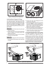
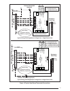
1. Route 24V control wires through the sealing
grommet (Figure 8, page 8) near the power
entrance.
2. Connect the control wires to the defrost
board and blower relay wire (Figure 10,
page 11).
• Several thermostat options are available
depending on the accessories installed with
the unit. Select a thermostat that operates in
conjunction with the installed accessories.
• The thermostat should be mounted about
5 feet above the fl oor on an inside wall. DO
NOT install the thermostat on an outside wall
or any other location where its operation may
be adversely affected by radiant heat from
fi replaces, sunlight, or lighting fi xtures, and
convective heat from warm air registers or
electrical appliances. Refer to the thermostat
manufacturer’s instruction sheet for detailed
mounting information.
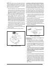
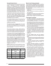
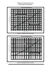
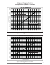
Demand Defrost Control
The demand defrost board controls the defrost
cycle in response to ambient temperature,
outdoor coil temperature and accumulated
compressor run time. The heat pump is allowed to
operate in the heating mode until the combination
of outdoor ambient and outdoor coil temperatures
indicate that defrosting is necessary, based on
the programmed defrost curve. There are four
preprogrammed defrost curves on the board. A
jumper pin is used to switch between the different
curves. The factory default setting is program
two. This is the recommended setting for most
standard applications. For differences between
the defrost curves, see Table 1.
The standard defrost cycle will terminate after
13 minutes and 39 seconds or when the coil
temperature reaches its terminate temperature,
whichever comes fi rst.
The defrost board is equipped with a 5 minute
Anti-Short Cycle Delay (ASCD). The compressor
will not turn on until the minimum 5 minute off
time is reached.
The control contains a forced - defrost feature,
which puts the system into defrost mode every 6
hours and 4 minutes, unless the coil temperature
is above the selected terminate temperature.
The system can be manually forced into defrost
mode at any time by shorting the TEST terminals
on the demand defrost board together for more
than 9 seconds. The coil temperature sensor
does not need to be cold when the unit is forced
into defrost. After the TEST input is removed, the
defrost mode will terminate in 13.7 minutes or
when the coil temperature is above the terminate
set-point or when the Y input is removed,
whichever occurs fi rst.
NOTE: If a demand curve is selected which has a
30 second compressor time delay in defrost, the
delayis reduced to 10 seconds in TEST mode.
Table 1. Demand Defrost Curve Profi les
Jumper
Position
Minimum Time
Between Defrosts
(min)
Terminate
Temp(° F)
120 40
220 40
320 32
420 75
Electric Heat Package (optional)
This heat pump is shipped without an auxiliary
electric heat kit installed. If electric heat is desired,
an accessory Heater Kit must be fi eld installed.
See Specifi cations Sheet for available kits and
their application.
• Select the correct size heat package for the
installation.
• Follow installation instructions provided with
each heater kit.
• Installation is most easily accomplished before
making duct or electrical connections.
• Refer to Table 4 (page 20) for blower speeds.