


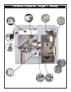
Installation
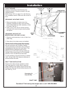
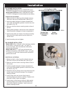
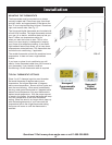
FIG. 9
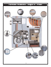
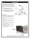
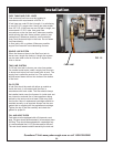
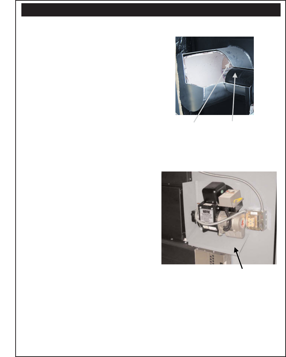
FIG. 10
OIL BURNER INSTALLATION
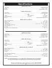
• Model LWO-112 burner has a (140,000 BTU input)
1.00 G.P.H. 80 degree H nozzle installed at the factory.
• Model LWO-168 burner has a (189,000 BTU input)
1.35 G.P.H. 80 degree H nozzle installed at the factory.
Install burner as follows:
1. Make sure hole in side of pyrolite chamber lines up
with hole in the end of the blast tube. (See Fig. 9)
2. Install drip shield (shipped in blower compartment)
over studs. Place gasket (packed in burner box) over
drip shield. (Fig. 10)
3. Remove nuts from burner mounting studs on face of
furnace.
4. Place gasket (packed on burner box) over studs and
install drip-shield. (Shipped in blower compartment.)
5. Insert burner tube into furnace. The burner mounting
flange should be tight against the drip-shield and
furnace front.
6. Install mounting nuts and tighten.
GAS BURNER INSTALLATION
• Model LWG-112 A 7/32" dia. orifice has been installed
at the factory. (140,000 BTU input - nat. gas). To
convert to LP gas, see manufacturers instructions
packed with the burner.
• Model LWG-168 A "F" (.257 dia.) orifice has been
installed at the factory (189,000 BTU input - nat. gas).
To convert to LP gas, see manufacturers instructions
packed with burner.
Install burner as follows:
1. Make sure hole in side of pyrolite chamber lines up
with hole in the end of the blast tube. (See Fig. 9)
2. Remove nuts from burner mounting studs on face of
the furnace.
3. Install drip shield (shipped in blower compartment)
over studs. Place gasket (packed in burner box) over
drip shield. (Fig. 10)
4. Assemble mounting flange over burner blast tube (flat
surface away from burner housing). Do not tighten
clamping screws.
5. Insert burner tube into furnace. Align holes in
mounting flange over studs on furnace. Replace nuts
removed in step 2 above and tighten.
6. Insert burner so that burner housing is tight against
mounting flange (end of blast tube should be flush
with inside of pyrolite chamber). Level burner and
tighten clamping screws.
Drip
Shield
CUT AWAY VIEW
BURNER COMBUSTION CHAMBER
Burner
Blast Tube
Pyrolite Liner
In combustion
Chamber
15