


292447-YIM-A-0507
Unitary Products Group 53
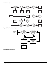
Burners/Orifices Inspection/Servicing
Before checking or changing burners, pilot or orifices, CLOSE
MAIN MANUAL SHUT-OFF VALVE AND SHUT OFF ALL
POWER TO THE UNIT.
1. Open the union fitting just upstream of the unit gas valve
and downstream from the main manual shut-off valve in
the gas supply line.
2. Remove the screws holding each end of the manifold to the
manifold supports.
3. Disconnect wiring to the gas valves and spark igniter(s).
Remove the manifold & gas valve assembly. Orifices can
now be inspected and/or replaced.
To service burners, complete step 4.
4. Remove the heat shield on top of the manifold supports.
Burners are now accessible for inspection and/or
replacement.
NOTE: Reverse the above procedure to replace the
assemblies.
Make sure that burners are level and seat at the rear of the gas
orifice.
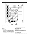
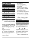
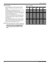
Figure 32: Typical Flame
Figure 33: Typical Gas Valve
Charging The Unit
All ZR units use Thermal Expansion Devices. Charge the unit to
10° subcooling.
Troubleshooting
Predator
®
Flash Codes
Various flash codes are utilized by the unit control board (UCB)
to aid in troubleshooting. Flash codes are distinguished by the
short on and off cycle used (approximately 200ms on and
200ms off). To show normal operation, the control board
flashes a 1 second on, 1 second off "heartbeat" during normal
operation. This is to verify that the UCB is functioning correctly.
Do not confuse this with an error flash code. To prevent
confusion, a 1-flash, flash code is not used.
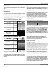
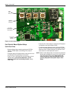
Alarm condition codes are flashed on the UCB lower left Red
LED, See Figure 34. While the alarm code is being flashed, it
will also be shown by the other LEDs: lit continuously while the
alarm is being flashed. The total of the continuously lit LEDs
equates to the number of flashes, and is shown in the table.
Pressing and releasing the LAST ERROR button on the UCB
can check the alarm history. The UCB will cycle through the last
five (5) alarms, most recent to oldest, separating each alarm
flash code by approximately 2 seconds. In all cases, a flashing
Green LED will be used to indicate non-alarm condition.
In some cases, it may be necessary to "zero" the ASCD for the
compressors in order to perform troubleshooting. To reset all
ASCDs for one cycle, press and release the UCB TEST/
RESET button once.
Flash codes that do and do not represent alarms are listed in
Table 30.
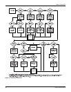
+($7(;&+$1*(578%(
%851(5)/$0(
%/8(21/<
,*1,725
%851(5%5$&.(7
%851(5
*$6
6833/<
3,3(
,1/(7
35(6685(
7$3
+,*+/2:*$6$'-8670(17
287/(7
35(6685(
7$3
0$7(1/2&.
&211(&7256
+,
/2
21
2))
09
&
+,
Troubleshooting of components may require opening
the electrical control box with the power connected to
the unit. Use extreme care when working with live
circuits! Check the unit nameplate for the correct line
voltage and set the voltmeter to the correct range before
making any connections with line terminals.
When not necessary, shut off all electric power to the
unit prior to any of the following maintenance
procedures so as to prevent personal injury.
Label all wires prior to disconnection when servicing
controls. Wiring errors can cause improper and
dangerous operation which could cause injury to person
and/or damage unit components. Verify proper
operation after servicing.