


292447-YIM-A-0507
48 Unitary Products Group
Safety Controls
The UCB monitors the temperature limit switch of electric heat
units.
The control circuit includes the following safety controls:
Limit Switch (Ls)
This control is located inside the heater compartment and is set
to open at the temperature indicated in the Electric Heat Limit
Setting Tables 22 and 23. It resets automatically. The limit
switch operates when a high temperature condition, caused by
inadequate supply air flow occurs, thus shutting down the
heater and energizing the blower.
Flash Codes
The UCB will initiate a flash code associated with errors within
the system. Refer to UNIT CONTROL BOARD FLASH CODES
Table 30.
Reset
Remove the call for heating by lowering the thermostat setting
lower than the conditioned space temperature.This resets any
flash codes.
Electric Heat Anticipator Setpoints
It is important that the anticipator setpoint be correct. Too high
of a setting will result in longer heat cycles and a greater
temperature swing in the conditioned space. Reducing the
value below the correct setpoint will give shorter “ON” cycles
and may result in the lowering of the temperature within the
conditioned space. Refer to Table 24 for the required electric
heat anticipator setting.
Gas Heating Sequence Of Operations
When the thermostat calls for the first stage of heating, the low-
voltage control circuit from “R” to “W1” is completed. A call for
heat passes through the UCB to the Ignition Control Board
(ICB). The UCB monitors the “W1” call and acts upon any call
for heat by monitoring the Gas Valve (GV). Once voltage has
been sensed at the GV, the UCB will initiate the fan on delay for
heating, energizing the indoor blower the specified delay has
elapsed.
When the thermostat has been satisfied, heating calls are
ceased. The GV is immediately closed. The blower is de-
energized after the fan off delay for heating has elapsed. The
draft motor performs a 30-second post purge.
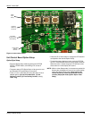
Ignition Control Board
First Stage Of Heating
When the ICB receives a call for first stage of heating, “W1,” the
draft motor is energized. Once the draft motor has been proven,
a 30-second purge is initiated. At the end of the purge, the GV
is opened, and the spark ignitor is energized for 10 seconds.
The ICB then checks for the presence of flame. If flame is
detected, the ICB enters a flame stabilization period. If flame
was not detected, the GV closes, and a retry operation begins.
During the flame stabilization period, a loss of the flame for 2
seconds will cause the GV to close and the retry operation to
begin. After the flame stabilization period, a loss of flame for 3/4
second will cause the GV to close and the retry operation to
begin.
At the conclusion of the flame stabilization period, the ICB will
operate the gas heat in high fire for an additional 60 seconds
(for a total for 120 seconds of high fire operation). After this 60
seconds, the ICB will then use the call for the second stage of
heat to control second stage operation of the GV.
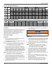
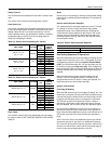
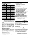
Table 23: Electric Heat Limit Setting 50” Cabinet
UNIT (TONS) VOLTAGE
HEATER
kW
LIMIT
SWITCH
OPENS °F
ZR102, 120, 150
(8.5, 10, 12.5)
208/230
18 150
24 150
34 150
54 130
ZR102, 120, 150
(8.5, 10, 12.5)
480
18 150
24 150
34 150
54 130
ZR102, 120, 150
(8.5, 10, 12.5)
600
18 150
24 150
34 150
54 130
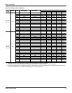
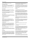
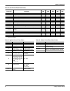
Table 24: Electric Heat Limit Setting 42” Cabinet
UNIT (TONS) VOLTAGE
HEATER
kW
LIMIT
SWITCH
OPENS °F
ZR078, 090 (6.5, 7.5) 208/230
9 135
18 150
24 165
34 190
ZR078, 090 (6.5, 7.5) 480
9 135
18 150
24 165
34 185
ZR078, 090 (6.5, 7.5) 600
9 135
18 150
24 150
34 185
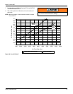
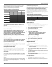
Table 25: Electric Heat Anticipator Setpoints
SETTING, AMPS
W1 W2
0.13 0.1