


292447-YIM-A-0507
Unitary Products Group 15
POE (polyolester) compressor lubricants are known to cause
long term damage to some synthetic roofing materials.
Procedures which risk oil leakage include, but are not limited to,
compressor replacement, repairing refrigerant leaks, replacing
refrigerant components such as filter drier, pressure switch,
metering device or coil.
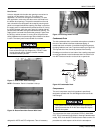
Units are shipped with compressor mountings which are
factory-adjusted and ready for operation.
Filters
Two-inch filters are supplied with each unit. One-inch filters may
be used with no modification to the filter racks. Filters must
always be installed ahead of evaporator coil and must be kept
clean or replaced with same size and type. Dirty filters reduce
the capacity of the unit and result in frosted coils or safety
shutdown. Refer to physical data tables, for the number and
size of filters needed for the unit. The unit should not be
operated without filters properly installed.
Power And Control Wiring
Field wiring to the unit, fuses, and disconnects must conform to
provisions of National Electrical Code (NEC), ANSI/NFPA No.
70 – Latest Edition (in U.S.A.), current Canadian Electrical
Code C221, and/or local ordinances. The unit must be
electrically grounded in accordance with NEC and CEC as
specified above and/or local codes.
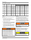
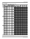
Voltage tolerances which must be maintained at the
compressor terminals during starting and running conditions are
indicated on the unit Rating Plate and Table 1.
The internal wiring harnesses furnished with this unit are an
integral part of the design certified unit. Field alteration to
comply with electrical codes should not be required. If any of
the wire supplied with the unit must be replaced, replacement
wire must be of the type shown on the wiring diagram and the
same minimum gauge as the replaced wire.
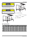
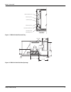
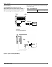
A disconnect must be utilized for these units. Factory installed
disconnects are available. If installing a disconnect (field
supplied or York International
®
supplied accessory), refer to
Figure 4 for the recommended mounting location.
NOTE: Since not all local codes allow the mounting of a
disconnect on the unit, please confirm compliance with
local code before mounting a disconnect on the unit.
Electrical line must be sized properly to carry the load. USE
COPPER CONDUCTORS ONLY. Each unit must be wired with
a separate branch circuit fed directly from the meter panel and
properly fused.
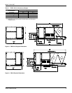
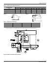
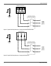
Refer to Figures 21, 22 and 23 for typical field wiring and to the
appropriate unit wiring diagram mounted inside control doors
for control circuit and power wiring information.
Power Wiring Detail
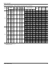
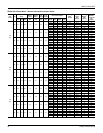
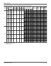
Units are factory wired for the voltage shown on the unit
nameplate. Refer to Electrical Data Table 8 to size power
wiring, fuses, and disconnect switch.
Power wiring is brought into the unit through the side of the unit
or the basepan inside the curb.
Do not leave the system open to the atmosphere. Unit
damage could occur due to moisture being absorbed by
the POE oil in the system. This type of oil is highly
susceptible to moisture absorption
Exposure, even if immediately cleaned up, may cause
embrittlement (leading to cracking) to occur in one year
or more. When performing any service that may risk
exposure of compressor oil to the roof, take precautions
to protect roofing.
Do not loosen compressor mounting bolts.
Make sure that panel latches are properly positioned on
the unit to maintain an airtight seal.
Avoid damage to internal components if drilling holes for
disconnect mounting.
When connecting electrical power and control wiring to
the unit, water-proof connectors must be used so that
water or moisture cannot be drawn into the unit during
normal operation. The above water-proofing conditions
will also apply when installing a field supplied disconnect
switch.