


292447-YIM-A-0507
40 Unitary Products Group
Air Balance
Start the supply air blower motor. Adjust the resistances in both
the supply and the return air duct systems to balance the air
distribution throughout the conditioned space. The job
specifications may require that this balancing be done by
someone other than the equipment installer.
Checking Air Quantity
Method One
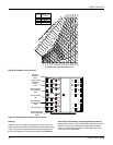
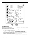
1. Remove the dot plugs from the duct panel (for location of
the dot plugs see Figures 12 and 13).
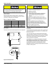
2. Insert eight-inches of 1/4 inch metal tubing into the airflow
on both sides of the indoor coil.
NOTE: The tubes must be inserted and held in a position
perpendicular to the air flow so that velocity pressure
will not affect the static pressure readings.
3. Use an Inclined Manometer or Magnehelic to determine
the pressure drop across a dry evaporator coil. Since the
moisture on an evaporator coil can vary greatly, measuring
the pressure drop across a wet coil under field conditions
could be inaccurate. To assure a dry coil, the compressors
should be de-activated while the test is being run.
NOTE: De-energize the compressors before taking any test
measurements to assure a dry evaporator coil.
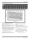
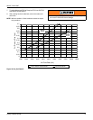
4. The CFM through the unit can be determined from the
pressure drop indicated by the manometer by referring to
Figure 30. In order to obtain an accurate measurement, be
certain that the air filters are clean.
5. To adjust Measured CFM to Required CFM, see SUPPLY
AIR DRIVE ADJUSTMENT.
6. After readings have been obtained, remove the tubes and
replace the dot plugs.
Method Two
1. Drill two 5/16 inch holes, one in the return air duct as close
to the inlet of the unit as possible, and another in the supply
air duct as close to the outlet of the unit as possible.
2. Using the whole drilled in step 1, insert eight inches of 1/4
inch metal tubing into the airflow of the return and supply
air ducts of the unit.
NOTE: The tubes must be inserted and held in position
perpendicular to the airflow so that velocity pressure
will not affect the static pressure readings.
3. Use an Inclined Manometer or Magnehelic to determine
the pressure drop across the unit. This is the External
Static Pressure (ESP). In order to obtain an accurate
measurement, be certain that the air filters are clean.
4. Determine the number of turns the variable motor sheave
is open.
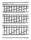
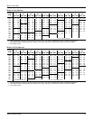
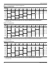
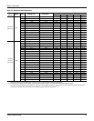
5. Select the correct blower performance table for the unit
from Tables 16 and 17. Tables are presented for side and
downflow configuration.
6. Determine the unit Measured CFM from the Blower
Performance Table, External Static Pressure and the
number of turns the variable motor sheave is open.
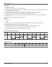
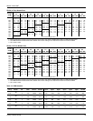
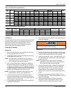
Table 19: Indoor Blower Specifications
Size
(Tons)
Model
Motor Motor Sheave Blower Sheave
Belt
HP RPM Eff. SF Frame
Datum Dia.
(in.)
Bore (in.) Model
Datum Dia.
(in.)
Bore (in.) Model
078
(6.5)
ZR
1-1/2 1725 0.8 1.15 56 3.4 - 4.4 7/8 1VM50 7.0 1 AK74 A49
2 1725 0.8 1.15 56 3.4 - 4.4 7/8 1VM50 6.0 1 AK64 A49
090
(7.5)
ZR
1-1/2 1725 0.8 1.15 56 3.4 - 4.4 7/8 1VM50 7.0 1 AK74 A49
3 1725 0.8 1.15 56 3.4 - 4.4 7/8 1VM50 5.7 1 AK61 A49
102
(8.5)
ZR
2 1725 0.8 1.15 56 3.4 - 4.4 7/8 1VM50 8.5 1 AK89 A56
3 1725 0.8 1.15 56 3.4 - 4.4 7/8 1VM50 7.0 1 AK74 A54
120
(10)
ZR
2 1725 0.8 1.15 56 3.4 - 4.4 7/8 1VM50 8.0 1 AK84 A56
3 1725 0.8 1.15 56 3.4 - 4.4 7/8 1VM50 7.0 1 AK74 A54
150
(12.5)
ZR
3 1725 0.8 1.15 56 3.4 - 4.4 7/8 1VM50 7.0 1 AK74 A54
5 1725 0.87 1.15 184T 4.3 - 5.3 1-1/8 1VP56 6.7 1 BK77 BX55
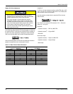
Table 20: Power Exhaust Specifications
Model Voltage
Motor Motor
Fuse Size
CFM @
0.1 ESP
HP RPM
1
1. Motors are multi-tapped and factory wired for high speed.
QTY LRA FLA MCA
2PE04703225 208/230-1-60 3/4 1075 1 7.8 5 6.3 10 3800
2PE04703246 460-1-60 3/4 1075 1 3.4 2.2 2.8 5 3800
2PE04703258 575-1-60 3/4 1050 1 2.9 1.5 1.9 4 3800
Failure to properly adjust the total system air quantity
can result in extensive blower damage.