


292447-YIM-A-0507
Unitary Products Group 49
When “W1” is satisfied, both valves are closed.
Second Stage Of Heating
When the ICB receives a call for the second stage of heating,
“W2,” the ICB conducts a complete first stage ignition
sequence. If this sequence is satisfied, the second main valve
of the GV is opened.
When “W2” is satisfied, the second main valve is closed.
Retry Operation
When a flame is lost or is not detected during an attempt to
achieve ignition, a retry operation occurs. A 30-second purge is
performed between ignition attempts.
If the unit fails after three ignition attempts, the furnace is
locked-out for one hour. The furnace is monitored during this
one-hour period for unsafe conditions.
Recycle Operation
When a flame is lost after the flame stabilization period, a recy-
cle operation occurs. If the unit fails after five recycle attempts,
the furnace is locked-out for one hour.
Gas Heating Operation Errors
Lock-Out
A one-hour lockout occurs following three retries or five
recycles. During the one-hour lockout, flame detection, limit
conditions, and main valves are tested. Any improper results
will cause the appropriate action to occur. Recycling the low
voltage power cancels the lock-out.
Temperature Limit
If the UCB senses zero volts from the high temperature limit,
the indoor blower motor is immediately energized. When the
UCB again senses 24 volts from the temperature limit, the draft
motor will perform a 15-second post-purge and the indoor
blower will be de-energized following the elapse of the fan off
delay for heating.
This limit is monitored regardless of unit operation status, i.e.
this limit is monitored at all times.
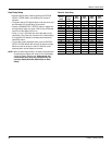
If the temperature limit opens three times within one hour, it will
lock-on the indoor blower motor and flash code is initiated (See
Table 30).
Flame Sense
Flame sensing occurs at all times. If “W1” is not present and a
flame is sensed for 2 seconds, the draft motor is energized and
the GV is kept off. The ICB halts any operation until a flame is
not detected. Once the flame detection is lost, the ICB performs
a post-purge. Normal operation is allowed concurrently with the
purge (i.e. this purge can be considered the purge associated
with a call for “W1”).
If “W1” is present, a flame is sensed, but the GV is not
energized, the draft motor is energized until the flame detection
is lost. Normal operation is now allowed.
The flame detection circuitry continually tests itself. If the ICB
finds the flame detection circuitry to be faulty, the ICB will not
permit an ignition sequence and the draft motor is energized. If
this failure should occur during an ignition cycle the failure is
counted as a recycle.
Gas Valve
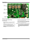
The UCB and ICB continuously monitor the GV.
If the ICB senses voltage at the GV when not requested, the
ICB will energize the draft motor. The ICB will not operate the
furnace until voltage is no longer sensed at the GV. The draft
motor is stopped when voltage is not sensed at the GV.
Any time the UCB senses voltage at the GV without a call for
heat for a continuous five-minute period, the UCB will lock-on
the indoor blower and a flash code is initiated (Table 30). When
voltage is no longer sensed at the GV, the UCB will de-energize
the indoor blower following the elapse of the fan off delay for
heating.
If voltage has been sensed at the GV for at least 15 seconds
during the fan on delay for heating and GV voltage or “W1” is
lost, the indoor blower is forced on for the length of the fan off
delay for heating.
During a call for heat, if the UCB does not sense voltage at the
GV for a continuous five-minute period the UCB will initiate a
flash code (Table 30). The indoor blower motor will not be
locked-on while there is no GV voltage.
Safety Controls
The UCB monitors the temperature limit switch of gas heat
units.
The control circuit includes the following safety controls:
Limit Switch (LS)
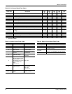
This control is located inside the gas heat compartment and is
set to open at the temperature indicated in the Gas Heat Limit
Control Settings Table 25. It resets automatically. The limit
switch operates when a high temperature condition, caused by
inadequate supply air flow occurs, thus shutting down the
heater and energizing the blower.
Auxiliary Limit Switch (ALS)
This control is located inside the supply air compartment and is
set to open at the temperature indicated in the Gas Heat Limit
Control Settings Table 25. It resets manually. The limit switch
operates when a high temperature condition, caused by
inadequate supply air flow occurs, thus shutting down the
heater and energizing the blower.
The auxiliary limit switch is wired in series with the limit switch.
As such, the UCB cannot distinguish the auxiliary limit and the