


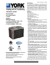
036-21137-004 Rev. C (0505)
2 Unitary Products Group
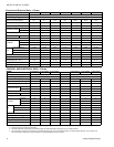
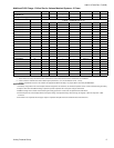
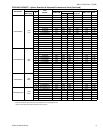
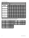
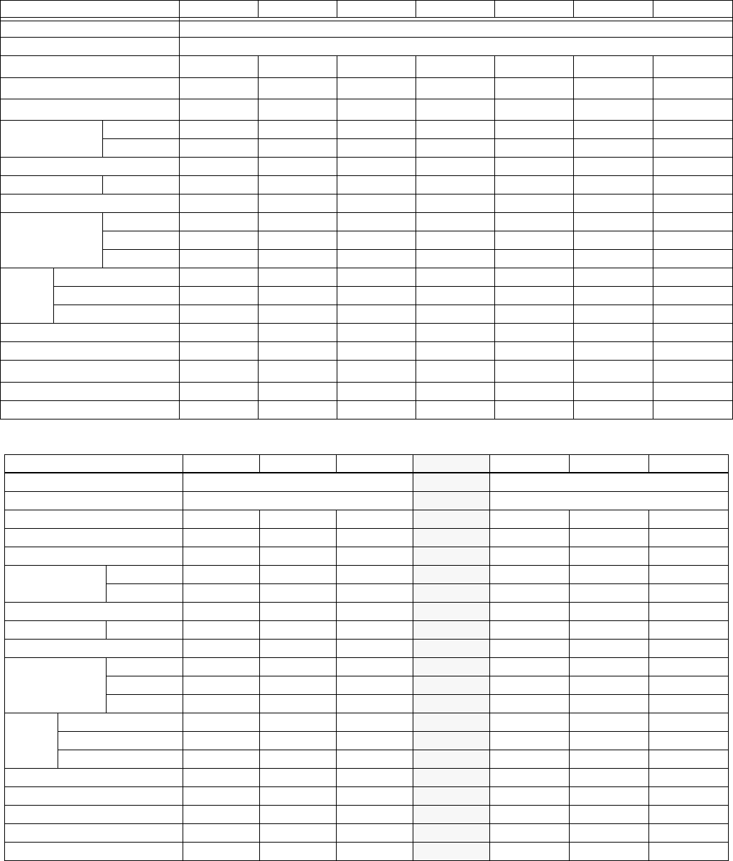
Physical and Electrical Data - 1 Phase
MODEL H2RC018S06 H2RC024S06 H2RC030S06 H2RC036S06 H2RC042S06 H2RC048S06 H4RC060S06
Unit Supply Voltage 208/230 – 1 – 60
Normal Voltage Range 187 to 252
Minimum Circuit Ampacity
1
10.1 14.1 16.5 19.7 26.2 28.5 37.5
Max. Overcurrent Device Amps
2
15 25 25 30 45 50 60
Compressor Type
3
Recip Inertia Recip Recip
Scroll
B
Recip
Scroll
B
Compressor Amps
Rated Load 7.7 10.9 12.8 14.7 19.9 21.8 28.8
Locked Rotor 48 60 68 82 115 105 145
Crankcase Heater No No No Yes No No No
Fan Motor Amps Rated Load 0.5 0.5 0.5 1.3 1.3 1.3 1.5
Fan Diameter Inches 18 18 22 22 22 22 22
Fan Motor
Rated HP 1/12 1/12 1/15 1/4 1/4 1/4 1/4
Nominal RPM 1,100 1,100 850 850 850 850 850
Nominal CFM 2,000 2,000 2,300 3,300 3,300 3,300 3,450
Coil
Face Area Sq. Ft. 12.58 12.58 15.72 15.72 17.03 19.65 23.58
Rows Deep 1 1 1 1 1 1 1
Fin / Inches 18 18 18 18 18 18 22
Liquid Line OD 3/8 3/8 3/8 3/8 3/8 3/8 3/8
Vapor Line OD 3/4 3/4 3/4 3/4 7/8 7/8 1-1/8
Unit Charge (Lbs. - Oz.)
4
4 - 9 4 - 7 5 - 8 5 - 3 6 - 13 7 - 7 8 - 15
Charge Per Foot, Oz. 0.68 0.68 0.68 0.68 0.70 0.70 0.76
Operating Weight Lbs. 144 146 156 161 157 190 198
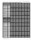
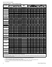
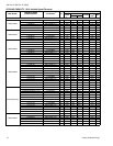
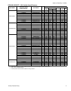
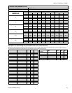
PHYSICAL AND ELECTRICAL DATA - 3 Phase
MODEL H1RC036S25 H1RC048S25 H1RC060S25 H1RC036S46 H1RC048S46 H1RC060S46
Unit Supply Voltage 208/230 – 3 – 60
460 - 3 - 60
Normal Voltage Range
1
187 to 252 432 to 504
Minimum Circuit Ampacity 13.3 18.9 22.9
7.6 9.6 12.0
Max. Overcurrent Device Amps
2
20 30 40 15 15 20
Compressor Type Inertia Inertia Scroll
Inertia Inertia Scroll
Compressor Amps
Rated Load 9.6 14.1 17.3
5.4 7.0 9.0
Locked Rotor 78.0 130.0 123.0
40.0 64.0 62.0
Crankcase Heater No No No
No No No
Fan Motor Amps Rated Load 1.3 1.3 1.3
0.8 0.8 0.8
Fan Diameter Inches 22 22 22
22 22 22
Fan Motor
Rated HP 1/4 1/4 1/4
1/4 1/4 1/4
Nominal RPM 850 850 850
850 850 850
Nominal CFM 3,300 3,300 3,400
3,300 3,300 3,400
Coil
Face Area Sq. Ft. 15.72 17.03 23.58
15.72 17.03 23.58
Rows Deep 1 1 1
111
Fin / Inches 18 18 18
18 18 18
Liquid Line OD 3/8 3/8 3/8
3/8 3/8 3/8
Vapor Line OD 3/4 7/8 1-1/8
3/4 7/8 1-1/8
Unit Charge (Lbs. - Oz.)
4
6 - 2 7 - 10 9 - 3 6 - 2 7 - 10 9 - 3
Charge Per Foot, Oz. 0.68 0.70 0.76
0.68 0.70 0.76
Operating Weight Lbs. 157 184 198
157 184 198
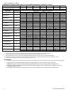
1. Rated in accordance with ARI Standard 110, utilization range “A”.
2. Dual element fuses or HACR circuit breaker.
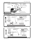
3. All scrolls listed with a superscript “B” are Bristol scrolls. All scrolls listed with a superscript “C” are Copeland scrolls.
4. The Unit Charge is correct for the outdoor unit, matched indoor coil and 15 feet of refrigerant tubing. For tubing lengths other than 15 feet, add or sub-
tract the amount of refrigerant, using the difference in length multiplied by the per foot value.