


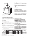
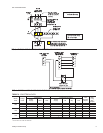
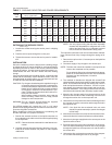


EXTENDING THE SERVICE PORTS
(Refer to Fig 7.)
1. Loosen the screws securing the service ports in shipping
position.
2. Push the service ports through the corner post.
3. Tighten the screws to secure the service ports for installa
-
tion.
INSTALLATION
Since the condensing units are shipped with a holding charge
of refrigerant-22, they can be checked for a refrigerant leak by
depressing the stem on either of the service ports that extend
through the cabinet. As soon as some internal pressure is re-
lieved release the stem. DO NOT release the entire holding
charge.
If the unit has already lost its holding charge, it should be leak
tested and the necessary repairs should be made. If the unit
has maintained its holding charge, you can assume that it has
no leaks and proceed with the installation.
CAUTION: Dry nitrogen should always be supplied through a
connectionwhile itisbeing brazedorunbrazed be
-
causethe temperaturerequired tomakeor breaka
brazed joint is sufficiently high to cause oxidation
of the copper unless an inert atmosphere is pro
-
vided.Theflowofnitrogen shouldbecontinuedun
-
til the joint has cooled.
When making a braze connection, wrap a wet rag
around all tubing inside the unit to help prevent
damage to other components.
WARNING:The dry nitrogen should always be supplied
through a pressure regulating valve.
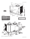
On HCE090 models only, remove the 4-1/2" x 4-1/2" patch
platesfromthepipingaccesspanelonthefrontoftheunitto ex
-
pose the refrigerant connections.
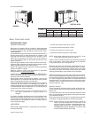
Before installing the liquid line between the condensing unit
and the evaporator coil, prepare as follows:
1. Burnish the external surfaces of the liquid connection on
the condensingunit andthe end ofthe field-suppliedpiping
for the liquid line.
NOTE: Clean surfacesare essentialfora well-brazedcon
-
nection.
2. Carefully clean the internal surfacesof the above. Any par
-
ticles left on these surfaces may lead to a future system
malfunction.
NOTE: Use only copper tubing that has been especially
cleaned and dehydrated for refrigerant use. If the
tubing has been open for an extended period of
time, it should be cleaned before being used.
The liquid line connections can now be brazed while maintain
-
ing a minimum flow of dry nitrogen through the piping as fol
-
lows:
1. Remove the capfrom the 1/4" accessport on theliquid line
service valve.
2. Connect a supply of dry nitrogen to this access port.
NOTE: The filter-drier should be installed in the liquid line as
close to the evaporator coil as possible.
Donot allowthe filter-drier tobe exposedto theatmos-
phere for an extended period of time. Once it absorbs
moisture from the atmosphere, it loses its
effectiveness.
3. The matched air handlers are shipped with a small R-22
charge and they should bechecked for leaks before instal
-
lation. Drill a small hole through the sealing cap or disc in
both the liquid and suction connection. If there is a pres
-
sure release,the evaporatorhas noleaks andyou canpro
-
ceed with installation. If the chargehas been lost, the coils
should be leak tested and the necessary repairs made.
4. Move the dry nitrogen supply from the access port on the
liquid line service valve of the condensing unit to the hole
through the suction disc on the evaporator coil.
5. Unbraze thecoil'sliquid linediscwhile maintainingaflow of
dry nitrogen across the connection and through the hole in
the liquid line disc.
NOTE: If the liquid line has a solenoid valve, the valve
should be opened manually to permit the nitrogen
to flow freely.
6. After the disc has been removed, burnish the external sur
-
faces and clean the internal surfaces as outlined above.
7. Move thedrynitrogen supplybackto theaccess portonthe
liquid line service valve.
8. Braze the liquid line to the liquid connection on the evapo
-
rator coil while maintaining a minimum flow of dry nitrogen
through the liquid line, the evaporator coil and the hole in
the suction disc.
9. Unbraze thedisc onthe suctionconnection oftheevapora
-
tor coil while maintaining the flow of dry nitrogen.
035-15407-002-B-0404
Unitary Products Group 9
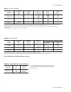
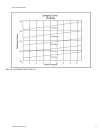
Model
HCE
Suction Press. & Corresponding
Temp. @ Saturation
Temperature of Air on Condenser Coil, °F
65 75 85 95 105 115
PSIG
°F
MBH KW* MBH KW* MBH KW* MBH KW* MBH KW* MBH KW*
090 61.6 35 90 6.1 88 6.7 81 7.2 77 7.9 74 8.6 68 9.5
68.5 40 101 6.3 96 6.8 91 7.4 87 8.1 82 8.9 77 9.7
76.0 45 110 6.5 109 7.0 101 7.6 95 8.4 90 9.1 85 10.0
84.0 50 120 6.6 115 7.2 109 7.8 104 8.6 99 9.4 93 10.3
120 61.6 35 123 7.7 117 8.4 112 9.1 106 9.9 100 10.8 95 11.8
68.5 40 134 8.0 128 8.6 122 9.3 116 10.1 110 11.0 104 12.1
76.0 45 145 8.2 139 8.8 132 9.5 126 10.4 120 11.3 113 12.3
84.0 50 156 8.4 150 9.1 143 9.8 136 10.6 129 11.5 123 12.5
150
61.6 35 140 9.4 133 10.4 127 11.3 119 12.6 112 13.8 105 15.1
68.5 40 151 9.6 144 10.6 137 11.5 129 12.8 122 14.1 114 15.4
76.0 45 165 9.9 156 10.9 148 11.8 140 13.1 132 14.4 124 15.8
84.0 50 178 10.2 169 11.2 159 12.1 151 13.4 142 14.8 134 16.1
* Includes compressor and condenser fan motor(s).
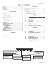
TABLE 7 - COOLING CAPACITIES AND POWER REQUIREMENTS