


10. After the disc has been removed, burnish the external sur
-
faces and clean the internal surfaces as outlined above.
The suction piping can now be brazed to the suction
connection on the evaporator coil while maintaining a
minimum flow of dry nitrogen.
Before brazing the suction line to the condensing unit;
1. Move the drynitrogen supply tothe access porton the suc
-
tion service valve of the condensing unit.
2. Burnish the external surfaces and clean the internal sur
-
facesofboththesuctionconnectionandthesuctionpiping.
The suction line can now be brazed to the suction con
-
nection on the condensing unit while maintaining the
flow of dry nitrogen.
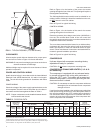
After the liquid and suction lines have been installed,
the system should be evacuated and charged.
EVACUATION AND CHARGING
Withtheliquidandsuctionlineservicevalvesclosed,connecta
vacuum pump througha charging manifold to theaccess ports
on both the liquid and suction line service valves.
Note: The vacuumpumpconnection shouldbe shortand
no smaller than 3/8" O.D.
Therefrigerant linesandthe evaporatorcoil cannow beevacu-
ated to 500 Microns without disturbing the charge in the con-
denser coil or the compressor.
After proper evacuation and dehydration, charge refrigerant
throughthe accessport onthe liquidline servicevalve allowing
the vacuum to draw in as much refrigerant as possible.
CAUTION: Do not charge liquid refrigerant through the com-
pressor suction connection.
CAUTION: Do not attempt to start the compressor without at
least 8 hours of crankcase heat or compressor
damage will occur.
To continue charging refrigerant, open the liquid and the suc
-
tion lineservice valves fully. Turn the stemof the liquidservice
valve clockwise 1/4 turn to open its access port for reading
pressure.
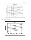
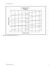
Startthecompressor (after8hours ofcrankcase heat),turnthe
stem ofthesuction lineservice valveclockwise
1
/
4
turn toopen
its service port and continue to charge refrigerant gas through
thissuction accessport untilyoumeet theconditions shownon
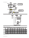
the charging curve, Fig. 8-10
.
Open theliquid andvapor lineservice valvesfully toclose their
access ports after the system has been charged.
Alternate Charging Methods
If you are starting a unit when the ambient temperature is
higher or lower than those shown in Fig. 8-10, either of the fol
-
lowing methods may be used.
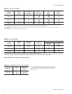
Method 1: Determine thetotal weight ofthe refrigerant forthe
total system by adding the required charge for the
outdoor unit, the indoor unit and the refrigerant
lines using information in Tables 2 (Physical Data)
and 6 (Refrigerant Line Charge).
Using the charging procedures outlined above,
weigh the required amount of refrigerant charge
into the unit.
Method 2: Install a field supplied moisture indicating sight
glass in the liquid line between the filter-drier and
the evaporator coil.
Using the charging procedure outlined above,
charge refrigerant until the moisture indicating
sight glass is clear. Add approximately 1 extra
pound of refrigerant for the 090 and 120 or 3 extra
pounds for the 150 to assure a liquid refrigerant
seal at the expansion valve under all operating
conditions. Block the flow of the condenser air, if
necessary, to assure a head pressure of 280 psig
during the charging procedure.
Note: The installer should return to the job to verify the
operatingchargewhen theambient temperatureis
within the conditions shown in Fig. 8-10.
035-15407-002-B-0404
10 Unitary Products Group